Several months ago after slightly reworking the wiring to the J-head, the thermistor slipped slightly loose from its socket in the heater block. The temperature monitoring code in the controller will detect a short or open connection on the thermistor and shut down the heater, but it can't do anything to detect a thermistor that is simply no longer thermally connected to the block, and the heater stayed on long enough to drive the heater block far above its normal operating temperature. I knew something was wrong when the plastic coming out of the nozzle was bubbling. Fortunately I noticed and shut the printer down before the plastic J-head barrel was completely ruined, but there was still damage done. Ever since then the head's been prone to jamming, hard to feed filament into, and reluctant to let go of the filament when I'm trying to change colors.
I noticed a marked drop in reliability while printing the second version of my Tardis Transformer. Trying to print faster than 30mm/sec inevitably led to a complete filament jam, often requiring a complete dis-assembly of the entire extruder from hot end to pinch wheel to fix. Finally the entire thing jammed up with a plug of plastic in the barrel that just couldn't remove without destroying the J-head. Fortunately I had already ordered another J-head, this one with a 0.35mm nozzle as I wanted to experiment with printing more detailed part.

Here's the new head, mounted in the plastic carrier that I use to attach it to the end effector on my printer. The carrier is two pieces of PLA that clamp the end of the J-head, with guide holes for wires and a place for the push-fit connector to screw in. In theory, I shouldn't be using PLA to clamp the hot end, since the hot end gets more than hot enough to melt PLA. In practice, the top end of the plastic barrel never seems to get even close to being hot enough to damage the plastic clamp.
The new J-head seems to be using a different kind of plastic than the previous one was, dark-colored as opposed to the pale tan of the older one. I'm not sure if this makes any difference, I suspect not.
 Wiring the hot end is always tricky. This part of the printer sees constant vibration, and the wires need to be able to flex freely yet not crack from flexing or vibration. I've secured the heater resistor and thermistor into the heater block with fire putty, and additionally secured the thermistor cable to the J-head barrel with heat-shrink and copper jewelry wire. This should help keep it from pulling out of the head again, as well as help protect the fragile thermistor wires from vibration-induced failure.
The main downside to moving to a smaller nozzle is that it will take more force to push filament through the nozzle. Rostock-derived printers already need a lot of force, with the long Bowden tube and (ideally) high print speed, and even with a 0.5mm nozzle it's not hard to exceed the torque your stepper motor and motor driver chips can deliver. Fortunately I'd installed a geared extruder on my printer months ago, while trying to push the upper end of its printing speed.
 I could have bought a geared stepper motor, or fit a gearbox on to my existing stepper, but to save money I decided to try and build my own gearbox first. I got the idea after printing this amazing 6-speed automatic transmission model. Printing and building it convinced me that the quality of parts from my printer were high enough to actually make working gears, so I set about designing my own geared extruder. While the gear teeth were perfectly fine, the plastic-on-plastic bearings had far too much friction for an actual functional part, so my gearbox was designed to have R4RS bearings (chosen because I had 10 of them on hand) pressed into each gear.
I also replaced the plastic pins in the original transmission with metal shafts. Here I'm using three 1/4" shoulder bolts (again, chosen because I had them on hand) with the heads cut off to couple the planet gears to the gear carrier, and a M5 machine screw as the shaft to connect the carrier to the filament drive pulley. Using a machine screw as an output shaft is sadly not optimal. I've managed to size it so the drive pulley is completely on the unthreaded part of the bolt (rather than resting on the threads), but the bolt isn't exactly the same diameter as the bore of the pulley, so there's a little bit of eccentricity as it turns. That translates to a slight variance in punch pressure as the extruder runs. This doesn't seem to be a problem yet, but I'd really like to replace that part with something custom-machined.

The extruder itself started off as a modified Airtripper design, but as is typical I've completely redesigned it from scratch. Rather than two or four compression bolts I have a single bolt with a large hand-friendly knob pressed onto it. This lets me easily and without any tools adjust the pressure on the filament. It also lets me easily unclamp the pinch mechanism to completely release the filament, which I prefer to do when changing filament colors. It's still not an ideal design - it takes a lot of turns to completely release the filament, and the threads on the screw strip after a few hundred cycles. I've been meaning to redesign this with some kind of clever fast-release over-center clamp mechanism.

The completed extruder is admittedly huge. The plastic gears work wonderfully, and have run for hundreds of hours of printing without any problems, but I did have to make them fairly large to handle the load. A metal gearbox wouldn't have been any wider than the motor itself. It's not really a problem since the extruder doesn't need to move or fit in a compact space, but can just sit out of the way at the top of the printer.

Looking up into the top of the printer. The extruder mechanism is at the center. The filament reel is on the top of the printer, with the filament fed down through a hole in the center of the upper plate. Two small white LEDs are aimed at the point where the filament is pressed against the drive pulley, these cast enough light on that spot to let me see the filament drive is working properly. I also have three fans arranged around the top end blowing air down into the print volume. I'm not sure if these do much useful, but they look kind of cool. You can also see my cheap little printed cable clamps, the heatsink for the 5V regulator for the fans and LEDs, and the terminal blocks which let me easily disconnect the cables to the end effector.
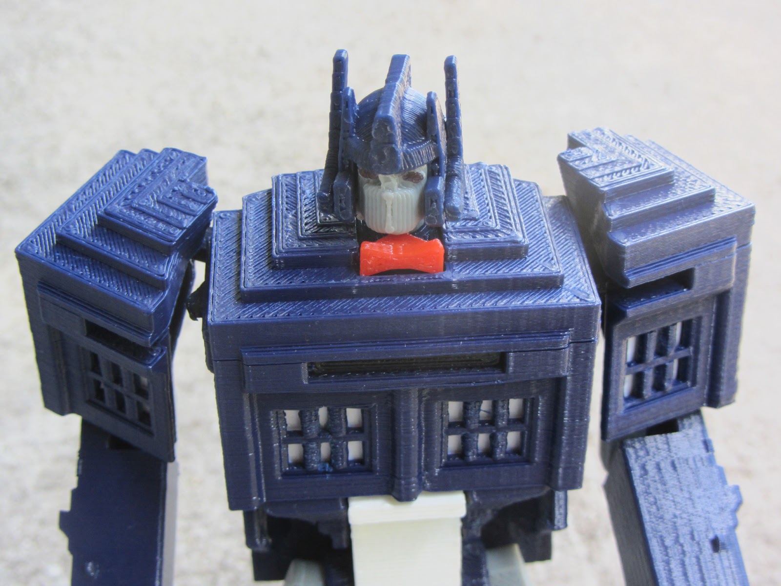
In addition to replacing the J-head, I've been experimenting with smaller layer height. The default layer height setting on Slic3r is 0.4mm, which worked well enough for me when using my old 0.5mm nozzle. The first few prints with the new nozzle were at 0.3mm, which along with the smaller nozzle made a noticeable improvement in print quality. I tried pushing the layer height smaller, and discovered the microlayering function in Slic3r, which allows you to have different layer heights for perimeter and infill layers. Unfortunately, when I tried printing objects at 0.135mm (with 0.27mm infill) I ran into an annoying bug where the printer would consistently freeze up mid-print when printing certain objects. I've backed off to 0.18mm (with 0.36mm infill) which seems to be a sweet spot for reliability and detail on my printer.
Why those particular oddball heights? My printer uses 36 tooth, 2mm pitch pulleys, motors with 1.8 degree step angle, and motor drivers with 16:1 microstepping. If I've done the math correctly, that means that the physical resolution limit of my printer is 0.0225mm. I had the idea that for consistent prints the layer Z-height should be an integral multiple of this resolution. 0.18mm is exactly 8 times the resolution limit, or equal to one half of a full 1.8 degree step of the motor, and the 0.36mm infill is happening exactly once per full step. Given the way that a Delta printer works, where the physical Z height is determined by the combined action of three different motors, this may not matter as much as it would for a conventional cartesian axis printer. I figure it doesn't hurt either, and with the 0.18mm/0.36mm layer height I'm getting some amazing print quality.