For demonstrations at various parties and family gatherings over the holidays I have rebuilt the walking robot. The issues which arose with the robot over the summer appeared to be due to the unsatisfactory reliability and poor accuracy of the cheap HX12K / MG995 servos. The combination of the higher than recommended voltage and amble gait was too much for the motors, which were failing frequently, but what was most unacceptable was the terrible servo feedback loops which made the entire robot shake uncontrollably when trying to hold a leg in the air.
I can't afford to buy 8 new higher-quality servos at the moment, and most of the choices of servos designed for operation above 6 volts would require significant redesign of the entire robot. I did have on hand the 8 HS5645MG servos used on the previous version of the robot. I had stopped using them because of the high rate of gearbox failure in that design, but the electrical and structural failure rate of the HX12K servos was a lot worse. I had also cut the mounting flanges off all those servos as on the previous version I was epoxying the servos to the robot structure.
The new chassis needs servos to be mounted by their mounting tabs, so I couldn't use the old servos as-is. Here I was in luck. Dissassembly and comparison of the HS5645MG and HX12K reveals them to be suspiciously similar internally. The HX12K / MG995 appears to be basically a cheap knockoff version of the HS5645MG, similar enough that I was able to take the electrical and mechanical guts of the HS5645MG and install them inside a HX12K case. I haven't figured out a way to use the HX12K gear train with the HS5645MG electronics and motor yet, so I'm still using the more fragile HS5645MG gears. The gears have the same pitch diameters and axles, which lets me install the gears from one servo in the case of another, but the tooth count is different so I can't mix build a hybrid gear train from both.
The HX12K does have somewhat flimsy mounting tabs, several of which failed at GenCon. For the rebuild I dug through my junkbox and found the largest rubber grommets and ferrules I had, in an attempt to spread the load out as much as possible. This is admittedly a temporary solution. I am still looking into ways to reinforce the servo cases where they mount to the frame.
One surprise when wiring up and testing everything is that the HX12K and HS5645MG seem to have the opposite direction of movement in response to servo commands. When adjusting the mixing logic and pre-programmed poses in the controller I'm having to change signs and invert position settings throughout the code. Although it's possible this is the result of something I did when rebuilding the servos and robot - I might have accidentally reversed the connections between servos on the left and right sides of the robot or something.
At the moment the robot seems to be working well, and held up for several days with family and friends through the holidays. I haven't stripped any more gears yet, but it remains to be seen if this is just a matter of time, or if the shock absorbers and other structural design improvements are actually making a difference.
Monday, December 28, 2009
Saturday, October 31, 2009
Shiny uranium bauble
My project for this weekend was to build a little decorative bauble, a piece of electronic jewelry. Seven high-brightness UV leds driven by a ring oscillator circuit arranged around a uranium-glass marble. You can see a few pictures of it here.
Some of you may recognize this as being similar to the power indicator on my walking robot. The difference with this piece, other than being stand-alone, is that the LEDs are made to flash sequentially rather than being on all the time. It makes it a lot more eye-catching.
Several of my friends are encouraging me to make and sell these as steampunk jewelry. That might end up being the only way I can afford new servos for the robot.
Friday, October 30, 2009
Looking for servos...
The 2009 version of my walking robot was in part a test of the feasibility of using the cheap MG995 servo in a walking robot. I expected that even if these cheap servos didn't last long their cheapness meant replacing them wouldn't be unreasonably expensive. These servos lasted long enough in practice (although when they failed the failure mode what not what I expected) but their terrible position-holding ability made them unacceptable for what I'm trying to do. So the MG995 servos have to go.
I'm currently rebuilding the robot with some HS-5645 servos I have on hand, but I don't expect those to last long. One already has a stripped gear set, and the others don't look they have much life left in them.
I need new servos. Preferably metal-geared servos with motors rated for 7.4V lithium battery use. Unfortunately I'm also on a very tight budget for robots at the moment. My wife will only approve buying expensive servos if I can guarentee they will never fail, and who can guarentee that?
There's the HSR-8498HB. The low-end 7.4V robot servo from HiTec. Not cheap at $60, and a little less torque than the HS-5645MG. It has Karbonite gears, whose durability I would be very concerned about. The HSR-5498SG has steel gears, better torque, and is only slightly more expensive at $70. Both these servos are available with a rear axle point built into the case, which would remove the need for me to modify the case that way. On the downside these do not use the standard servo mounting points, which means they would not be useable with the current waterjet frame pieces. Although since all the strucural failures I had were at the standard mounting points, redesigning the servo-to-frame attachment method might be a good idea.
There's the $60 HDS-2288. Metal gears, rated for 7.4V, nice torque, uses standard servo mounting points. I'm not sure if they're actually available with any reliability, they seem to be sold out or on backorder everywhere.
The $20 Associated SHV1504MG has metal gears and is rated for 7.4V, and uses a standard servo case, but is terribly underpowered for this requirement.
Then Dynamixel servos. These look really interesting, having some amazing features way beyond normal servos in how they can be configured and what kind of feedback data you can get back from them. These don't use the standard servo control pulses at all, but instead have an addressed serial bus scheme, which I should be able to connect straight to the serial ports on the Xbee radio. I could use this to feed back voltage and temperature indications to the controller, maybe even translate joint torque into force-feedback somehow. Very interesting possibilities. And all these servos will run at 7.4V. They're actually designed for 9.6V, so 7.4V is a little on the low side but still within the rated voltage range.
On the down side most of the Dynamixel servos are completely outside my price range. The $45 AX-12 servo I could probably afford, but those have plastic gears which I'd prefer to avoid. The Dynamixel servos also would require a complete strucural redesign to use. That might be a plus after all, the AX-12 servos are far better suited to robotics from a strucural point of view than are standard hobby servos.
The last option would be to just make some frankenstein hack from my current servos, homemade die-cast cases, openservo boards, and rewound motors. Considering that as a backup plan.
Thursday, August 20, 2009
LiPolys and servos
Lithium-polymer batteries are inconvenient. They're physically fragile, awkwardly shaped (at least for fitting in cylindrical or spherical compartments), prone to turning into fireworks if mistreated, and have a nominal cell voltage of 3.7V. I can work around the shape and fragility, and installed a battery protection board to keep the cell from igniting, but the cell voltage is a real problem. Most cheaply and easily available servos are designed to operate at 4.8V or 6V, running off a 4 or 5 cell NiCad pack. One LiPoly cell is too low-voltage to run servos from, and two will deliver 7.4V nominal, and up to 8V when freshly charged.
I can't afford to use the high-end robot servos designed for 7.4V, but I also can't ignore the fact that LiPoly cells deliver three times the energy density of NiCads. So since 2007 I've been ignoring the manufacturer recommendations and running normal hobby servos off two-cell LiPOly packs. It's worked, mostly, and I think I'll keep doing it.
Looking at the components inside a typical digital servo does not reveal any obvious voltage limitation that would prevent operation over 6V. The components which limit the voltage at which the control circuit can operate are the motor drive FETs and the 3.3V voltage regulator for the microcontroller. The FETs in the MG-5645 servos have a breakdown voltage rating of 20V, which even assuming 2X overvoltage from EMF spikes should run safely off a 9.6V pack. The 3.3V regulator I can't find a datasheet for yet, but typically should have a maximum input voltage of at least 12V. Nothing on the PCB itself should fail to work at 7.4V.
The actual voltage limit seems to be in the servo motor. According to HiTec, the motor in their standard digital servos is limited to 6V. Now, back from my old robot combat days, I learned a lot about how much you could safely overvoltage motors, and just what caused them to fail when pushed to hard. Voltage alone does not destroy a motor. Armature windings can come apart from spinning the motor too fast, magnets demagnetized from too much current and heat, and too much load for too much time without enough cooling can cause the solder joints to simply melt, but voltage alone doesn't fry a motor. The actual point at which a motor will self-destruct is complicated and depends a lot on the gear ratio, actual load on the shaft, and thermal conditions.
It's probable that 6V is the point where these servos are rated for steady operation without failure. Pushing them past that increases the rate of failure, but the actual failure rate is also dependent on a lot of other factors including the quality of construction, load, and duty cycle. Running the MG-5645 servos at 7.4V, I had no failures of the motors or control boards, although I did break a lot of gear sets. The motors did get pretty hot after a few minutes of walking, but I didn't have any actually fail. With the HX12K servos I had two motors simply die, unsurprising considering their cheap construction. The MG996 servos will probably work no better at 7.4V. I may rebuild the robot with MG-5645 servos after all, since they seem to tolerate some degree of overvolting.
Wednesday, August 19, 2009
Post GenCon report!
The robot ran at GenCon, getting in about half a dozen full charge cycles in over about three days before it was past the point where I could keep it going. Ultimately while it did succeed at the goal of entertaining others and myself, the performance and reliability weren't quite what I had hoped.
As I'd expected, all the reliability problems were with the servos. Unexpectedly, I didn't have a single gear failure. No stripped or broken teeth on any of the gears, and even the issue with the press-fit third gear coming apart that I'd seen early on one servo during testing didn't come up. I did have failure of the mounting tabs on three of the servos. The plastic web where the servo mounting tabs meet the cases is very thin on these servos. These mounting tabs can take the loads created by the servo torque, but the bending and twisting forces induced by the way all the forces from each leg are transmitted through the servo mounts appear to be more than they can take. I had servo mounting tabs break off on three servos, and so far have found cracks in the case of one more servo.
I also had motor failures in two servos. In both cases while walking the robot suddenly lost all power, apparently due to the overcurrent trip on the battery protector board. In both cases once power was cycled one of the servos no longer functioned, not even in the passive motor-braking mode the servos default to on powerup. I had thought it due to controller board failures, but on disassembly and testing found both motors had failed open. I haven't taken apart the motors to find out while they failed yet, but I suspect heat-induced failure of the connections to the brushes, or the brush holders or springs.
I had expected these servos to have a high failure rate, and designed the robot for easy access to the servos, so even with the high failure rate of these servos I was able to keep the robot working until I ran out of unbroken servo cases. I wasn't happy about having to repair the robot as often as I was having to recharge it's batteries, but I wasn't completely surprised.
The bigger problem was the poor control I had over the robot's motion. The lifelike movements people like about the robot, and the ability to make fins and subtle movements to interact with the crowd, depends on the servos closely matching the movement of the joysticks. On that this version of the robot failed. First of all, the precision of the HX12K servos is utter crap. There's a huge amount of play in the geartrain, which combined with a badly tuned control loop in the servo control board means that the position signal you're sending to the servo is going to be treated as at most a rough suggestion as to the position you'd like the servo to hold. There's a huge amount of overshoot and ringing, the robot's legs wandering and shaking randomly even when sent a steady position signal. Standing still with all four legs on the ground the robot would be stable, but it would shake uncontrollably when holding a leg in the air, and walking was jerky and unsteady. It was a goods thing thing that the ability to invert the legs and walk either side up was always a crowd favorite, because the robot would frequently fall over while walking.
The other problem was that the radio link, which worked fine at home, was unreliable in a convention hall full of cell phones and other electronics. Control was unpredictable - sometimes it would work fine at up to 30 feet, sometimes it would intermittently lock up at less than 5 feet.
I'm also not happy with the Wii Nunchuk joysticks. I just don't get the same fine-control ability as I had with the RC airplane radio set I used to use.
The radio range issue can be easily corrected. At the moment I'm using the 1mW version of the XBee radios. The Pro version of the XBee radio has a transmitter power of 60mW. More power might be the brute force solution of the problem, but that's fine with me. I also have some ideas for rebuilding the controllers with better joysticks stripped out of an old RC airplane set.
The control issues with the servos I can't do anything about without replacing them. Poor position-holding seems to be an unsolvable issue with the MG995/HX12K servo. I suspect that even if I transplanted the control boards from the HS-5645MG servos in my junk box the insane amount of play in the geartrain would prevent them from being accurate enough for my needs.
Some of the more astute of you might wonder, if I've got nice high-quality Hs-5645MG servos in my junk box, why am I wasting my time with cheap import crap like the HX12K? It's because the HS-5645MG gearboxes kept failing. The HX12K servos, for all their faults, at least have bulletproof gears. I may try rebuilding the robot with my old HS-5645MG servos anyway - the spring shock absorbers I built into this version of the robot's legs may be enough to save the gears from failing. There is also a new servo out, the TowerPro MG996, which is an upgraded version of the MG995/HX12K servo with better accuracy and reliability, which I might buy and try out eventually. For the time being my budget is shot and my wife's patience with robots that break after a minute of walking is expended, so buying any new servos will have to wait.
Thursday, August 13, 2009
Servo failures
I had another servo failure today, after a lot of walking around and showing the robot off. I'm seeing an interesting pattern. It's always the two servos which move the rear legs horizontally which fail. These seem to be under the most strain, being the servos responsible for most of the forward/upward movement of the robot with each step. Surprisingly enough, the gears are not failing at all. The cases are. The mounting tabs which connect the servos to the robot chassis have cracked on two servos now. I am also seeing failure of the case at the point where the gear shafts are held in place. Over time the shafts wear away the plastic until the shafts can wobble enough for the gears to jam or come unmeshed.
I have seem this type of failure before. Now that the problems with stripped gears appear to be solved it seems the plastic servo case is the next weak link. I have some ideas for reinforcing the servos but the machining involved may beyond the capabilities of my workshop.
I have seem this type of failure before. Now that the problems with stripped gears appear to be solved it seems the plastic servo case is the next weak link. I have some ideas for reinforcing the servos but the machining involved may beyond the capabilities of my workshop.
Wednesday, August 12, 2009
Update - day 1 of GenCon
Walked the robot around at the GenCon Stink for a while until one of the servos suddenly stopped working. Gears are intact. Seems to be a dead control board, although nothing is obviously burned out. Swapped the servo and the robot is walking again. Also one slightly cracked servo case and one loose servo horn screw, both easily fixed.
Radio range seems to be a lot shorter than at home. I blame the large number of cell phones. Must invest in higher power transmitter module after convention.
Radio range seems to be a lot shorter than at home. I blame the large number of cell phones. Must invest in higher power transmitter module after convention.
Friday, August 7, 2009
Design goals for 2009 walker:
1. No structural joints made with glue or epoxy.
The first walking robot I made wasn't much more than servos, a battery pack and a radio receiver held together with silicone glue. That worked well enough as those robots were too feeble and lightweight to need much structural strength. Later, as I went to stronger servos, heavier batteries, and more rigid structure I experimented with various epoxies. To keep the weight down, I wanted to use the servo cases and batteries themselves as structural elements, which meant ignoring the intended mounting tabs and epoxying directly to the servos.
The glue and epoxy kept failing. In the end I had the best luck with cyanoacrylate superglues, but even those didn't hold reliably. And when I started showing the robot at conventions, gluing everything together had a second downside in making it much harder to easily replace broken parts. The final straw was when I switched from the hefty NiCad cells I had been using to LiPoly packs with minimal structural strength. When I needed to add a steel frame to take the place of the batteries that had previously made up the structural core, there wasn't much point in using glue rather than screws to attach to the servos.
When I set out to completely redesign the structure on the latest rebuild, I set a solid rule. No glued or epoxied structural joints. Everything structural would either be fastened with machine screws (if meant to be disassembled), or welded or soldered (if meant to be permanent).
I did end up having to use superglue to attach weld nuts (used to provide a second hinge point on each servo joint) to the inside of the servo cases. The glue is only needed to hold the nuts in place during assembly, as the screw which holds the hinge pin in place also holds the servo nut from coming loose. I also had to use gaffer's tape and zip-ties in a few spots to hold wires in place. Not an elegant solution, but acceptable for non-structural parts.
2. No purely decorative components
I've made the mistake in the past of loading decorative bodywork and cosmetic detailing on convention robots. On the 2006 version of the robot I built up complex anodized titanium bodywork around the servos and joints, with rubber tubing covering the servo and battery wires and thick aluminum tubes for the legs and central chassis. The result - excess weight, stiffness and interference in the joints, for bodywork and cable sheaths that the robot would work better without. That version walked about ten seconds before stripping a gearbox.
Faster battery drain and more frequent gear replacement made for less time walking the robot around and having fun. Having a robot that works reliably for a long time had to be my first priority. My second strict rule on this redesign was to have nothing on the robot which didn't in some way help the performance or reliability of the robot. This didn't mean no cosmetic details. It meant making those functional parts of the robot cosmetically interesting so I wouldn't have to add completely useless cosmetic parts. I was also willing to stretch my definition of what counted as a justifiable functional purpose. For example, the copper body shell technically serves the purpose of holding wiring in place out of the way of the legs, so that counts.
3. Easy to maintain
I've tried, and failed, to design the robot such that nothing breaks over the course of a busy weekend. Instead I've designed the current version for easy maintenance. Those parts which I carry spares for can be easily removed and replaced without having to break or cut anything. The servo gears which are the most frequently failing point can be replaced without even having to remove the servos from the robot.
Those parts which I don't have spares for can still be either removed for troubleshooting, or at least easily accessed by removing any bodywork and components around them. I don't at the moment have spares for the radio, the battery, the servo-control board, or many of the other internal components, but I can get to and troubleshoot all those parts in place easily. Having a thin waterjet-cut steel frame supporting an easily removable outer shell versus the closed-box structure on some previous designs makes maintenance a lot easier.
4. Safe for human contact
This robot is meant to be shown off at conventions, walking up to people, shaking hands, and even being picked up and handled. It needs to be able to do all this without injuring anyone. No sharp points or edges. I designed it with spherical and cylindrical body sections, and rounded feet rather than points. The antenna had to stick out somewhat, but I replaced the stiff wire antenna that came with the radio gear with a length of super-flexible wet-noodle wire.
It also means I had to try to avoid pinch points. The servos I'm using now have amazing torque, enough that a finger in the wrong place could be crushed if the robot moved while being held. Although the XBee radios are pretty good about rejecting bad data, I didn't want to rely on the control system to prevent any of the servos from moving at the wrong time. This robot is designed with large openings around the joints, with rounded edges on all the metal surfaces facing openings. This also helps with reliability - wide open joints with lots of clearance are a lot less likely to bind or jam, and make it easier to reach in and work on mechanical bits without taking the entire joint apart.
Thursday, August 6, 2009
On feet.
A lot of people ask me, mostly after seeing the robot slipping when trying to walk on smooth tile floors, wouldn't it work better with rubber pads on the feet? The answer has to do with how the robot walks and the kind of materials it's optimized for.
The little walking robot walks by moving its legs in diagonally opposed pairs, where at any time two legs are moving forwards and two are moving backwards. In theory, the two legs moving forwards are off the ground with only the two backwards-moving legs pushing against the ground. In practice, the robot makes no attempt to balance on two legs, so the reality is that while walking one leg will be raised, two will be pushing backwards against the ground, and one will be sliding forwards along the ground. The robot doesn't so much walk as flail at the ground and push itself forwards. It's cheesy, but it works.
Very early versions of the robot had big fat rubber pads for feet. These versions walked fairly well on smooth hard floors, although with a high current draw, but would bog down and get stuck on carpet. The effort to drag the rubber feet across carpet was too much for the weaker servos I was using back then. It wasn't until I tried covering the feet with electrical tape to make them more slippery that the robot was able to walk across carpet well. Traction, as it turned out, was less important than the ability to smoothly and freely move the feet, at least when moving across carpet or other high-friction materials.
The tape-covered rubber pads worked, but were an ugly solution and wore out quickly. I replaced them with hard nylon spheres. These were nearly optimal for walking on carpet, but a second problem arose. The nylon-geared servos broke developed an alarmingly high failure rate. The rubber feet had been cushioning the impacts from walking, and with hard feet I was averaging one blown servo for every ten minutes of walking. I switched to metal-geared servos, which helped but did not eliminate the problem. The latest version has spring-cushioned telescoping shock absorbers in the legs, which seems to be helping with servo reliability.
The optimal foot design depends on the surface walked on. My robot is meant for walking around convention halls, where carpeting is the most common surface. Trial and error has shown me that hard smooth feet work best with the sliding gait the robot uses. It does mean it slips a bit on hard smooth floor, and is especially hard to control when partly on carpet and partly on a hard surface.
Wednesday, August 5, 2009
FAQ
What is it?
A walking machine, radially symmetrical, having four legs with two degrees of freedom each, controlled through a wireless link from a hand-held controller based on two Wii Nunchucks.
What's it for?
Amusement and entertainment. Mine, and that of people at parties and conventions which I bring it to. I make no pretense of any practical use of the robot, but it seems to draw a crowd and entertain. The robot also serves as an excuse for me to learn new skills in crafts and robotics, an excuse for me to experiment with microcontrollers, radio gear, metal etching and polishing, leatherworking, welding, and other such.
Is this something you bought or made from a kit?
This robot was designed and built from scratch. I am using quite a few off-the-shelf parts, including the servos, radio gear, and electronics boards, but the overall design is original and not based on any robot kit or toy.
How long did this take to make?
That’s hard to say. Building an entertaining little walking robot has been a hobby of mine for years. This particular robot has been a two-year project, starting shortly after GenCon 2007, worked on intermittently on spare weekends and evenings. It started with what was originally intended as an upgrade and repair of an earlier robot that then turned into a rebuild nearly from scratch. That robot was in turn based on an even earlier (and much less successful) robot I had in 2006, and so on. The earliest version of this quadruped design was built nearly a decade ago. It barely worked, but was enough fun for me to keep playing around with.
If I had to rebuild this bot from parts and raw materials, I could probably do it in a few weekends, but that of course would not include the time spent on research and design.
How much did it cost?
On this version of the robot, I estimate I’ve spend about a thousand dollars. Some of that was spent on parts that never ended up being used or broke and had to be replaced. On the other had the bot also includes some materials recycled from junk and scrapyards, so the actual cost to reproduce it from scratch is hard to estimate.
Why did you make it?
Many years ago I used to compete in robot combat competitions. Robot Wars (when it was in the US), BattleBots, Robotica, and various other local events. The RC airplane radio sets I used always came with a handful of little hobby servos. Meant for RC airplane use, they were too small and weak for combat robots. One bored day I took a look at the small pile of spare servos in my junk box and decided to do something fun with them. The end result didn’t walk very well or for very long, but was fun enough for me to continue refining the idea.
Years later I upgraded the design with better servos and higher capacity batteries, ending up with something that could actually walk well for more than a minute. I was by this time getting bored with the robot, but decided at the last minute to bring it along on a trip to GenCon. I had great fun walking the robot around the competition and entertaining people, although by the end of the convention the bot was pretty much trashed. Since then I’ve been working to improve the reliability and battery life, as well as the expressiveness and crowd-friendliness of the robot.
Are you making robots like this for sale?
I’ve considered it, but I do not have any plans to do so at this time. This robot is a hand-made piece of mechanical art, which I am constantly tinkering with and improving. I am not confident in the reliability of this design yet, and for what I would need to charge for my time to build it and the parts and materials I would not feel right selling anything but an absolutely finished and reliable machine. If I was mass-producing these by the thousand with injection-molded plastic parts and assembly by sweatshops in China I could sell these at a reasonable price, but I have neither the interest nor the startup money to pursue that path.
I have been working on making electronic jewelry with similar design themes which I may be selling on a limited basis in the future. I could also probably be persuaded to do custom work on commission. I don’t intend to offer standard pre-made robot kits of this design.
What's it made from?
The primary chassis of the robot is made from a single piece of waterjet-cut steel plate from Big Blue Saw. I was originally reluctant to order parts made for the robot as I wanted as much of it as possible to be hand-made, but having parts custom-cut turned out to be a very good idea. I was able to get some very complex and organic pieces of metal made with great precision, which eliminated issues with servo alignment in previous versions. The steel frame also takes up very little of the limited internal space in the robot, yet provides secure mounting points for the servos, bodywork, battery, and other internal parts.
The shell of the main body was made from a three inch diameter copper tank float. Spherical because I wanted to go with a rounded, organic-feeling design, and copper because I was aiming for a sort of steampunk theme, with hand-cut openings for the legs. Outward from that are the four leg midsection pieces which were also hand-cut from 2 inch diameter aluminum tube. The outer segment of each leg has another waterjet-cut steel piece, with a welded steel tube housing a spring-loaded telescoping ankle segment in the end. The feet are brass knobs, into which the shoulder screws which make up the mobile part of the telescoping section screw into.
The electronics of the robot are fairly simple. For me this project was always about mechanical design and packaging, with control electronics a secondary concern. The robot runs off a 7.4V 1100mAh LiPoly battery. I use a pair of XBee radio modules for communication. A Pololu micro SSC board receives a serial data stream from the transmitter via the XBee radios and generates the control pulses for eight HX12K servos.
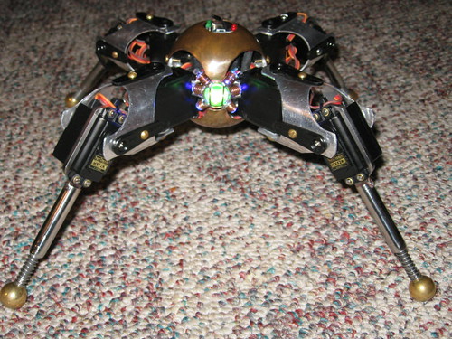
What's the glowey thing on the front?
The power indicator. It tells me the main power is on and shows which side of the robot is the front. It is made from a 5/8 inch uranium-glass marble held in a copper wire cage, surrounded by six high-power ultraviolet LEDs. The UV light from the LEDs makes the uranium-glass marble glow a nifty green color when the main power switch is on.
A rule I set for myself on this robot was that it would have no purely decorative parts. Functional parts could also be made decorative so long as their function was not impaired. Showing that the power is on and indicating which way is the front is to me more than enough function to justify a glowing marble and LED array.
How long does the battery last?
I’m really not sure. I’ve never run the robot non-stop from full power to battery exhaustion. I originally estimated half an hour of total run time, but that might have been an overly optimistic estimation.
Is that a Wii Nunchuck?
Two, actually. Previous versions of this robot used a RC airplane radio set for control, but for this version I wanted something less obvious and more compact. Something I could hold in one hand and conceal easily. The Wii Nunchuck is a pretty cool option – you get a joystick, triple-axis accelerometer, two buttons, and a housing with some extra space for a battery and radio for a pretty low price. I originally planned to use a single Nunchuck, controlling the motion of the robot with the joystick and accelerometer-sensed hand gestures. Along the way I decided I wanted a second joystick after all, so I bought a second Nunchuck for two-handed control. I also didn’t quite manage to fit the microcontroller and radio into the housing of the first one cleanly. The controller is a bit of an ugly hack – I intend to improve it cosmetically in the future, but for now just having it work was the priority.
What kind of electronics are in there?
The left-hand Wii Nunchuck is mostly unmodified. It has a joystick, accelerometer, and a microcontroller which samples sensor data and communicates over a serial data line. It is taped together because I opened it up before deciding to leave it functionally unmodified.
The right-hand Wii Nunchuck has been gutted and rebuilt. I removed all of the internal electronics except for the joystick and buttons, and installed a FunnelIO Arduino board, accelerometer, LiPoly battery, and XBee radio module from sparkfun. The accelerometer, joystick, and buttons in that unit are tied to the analog and digital inputs on the FunnelIO. The serial lines from the other Wii are tied into the SDA/SCL serial port on the Arduino. I use the Wii Nunchuk communication code from Windmeadow Labs (www.windmeadow.com) to get the data from the left-hand Nunchuck.
The Arduino takes the data from the unmodified Nunchuck, the analog values from the joystick and accelerometer on the modified Nunchuk, does some math to determine servo positions, and transmits serial data at 38400bps through the XBee radio link to the Pololu serial servo controller board in the robot. There’s also a battery management board in the robot which shuts off the battery in undervoltage, overvoltage, or overcurrent conditions.
I did not make any custom PCBs for this design. Previous versions of the robot did have custom-made PCBs, but thanks to Sparkfun and Pololu I was able to build the entire control and power system with off-the-shelf boards.
How do you control it?
Control of the robot is through the joysticks on the two Wii Nunchucks. I have some plans for control schemes based on accelerometer data in addition to the joysticks, but I haven’t implemented them yet. I will be experimenting with that in the future.
The control scheme for the robot does not use any pre-programmed sequencing. That is, all the movement of the legs is based on the immediate position of the joysticks and the mixing mode selected, so that in order to make the robot walk I have to move the sticks back and forth with each step. I had in previous versions had pre-programmed sequences for walking, but decided that manual leg control resulted in more fluid, lifelike motion, as well as a lot of flexibility for posing and gesturing.
There are multiple mixing algorithms I can choose from by pressing different combinations of the buttons on the Wii Nunchucks, depending on what I want the robot to do. I can also press a button which inverts the movement on the up/down servos and swaps the left and right servo movements. Because the body is top/bottom and left/right symmetrical, this lets me reconfigure the robot to walk upside-down if it flips over. Which it does fairly frequently.
The robot has essentially no on-board processing, other than that required for error-checking and decoding the serial data stream from the hand controller.
What's the radio range?
Not very long – about 20 feet before control becomes intermittent. I am using the lowest-power version of the XBee radios. I may move to the higher-power version in the future, if I want better range, but for now I don’t like to have the robot that far from me while controlling it.
Is this based on a Dragoon from Starcraft?
No. I’ve never even played Starcraft. I didn’t even know what a Dragoon was until I went and looked it up after enough people asked me if I’d based this on that design.
So where did the design come from?
As mentioned above the first version was built as something fun to do with leftover hobby servos. I had eight servos, so a robot with four legs, two servos per leg, worked out well. I was also at the time considering the challenge of making a walking robot for competition use. Working with cheap and weak servos and not having the budget for elaborate balancing systems, I looked at turtles for design inspiration. Rigid body, not much need to balance, four short stubby legs – seemed like I could do that. I made it with radial symmetry to keep the design simple and make it able to walk in any direction. Being able to walk upside-down didn’t come till much later.
I never ended up adapting the design for any competition. Making it to be a free-form entertainment robot was more fun for me.
How much does it weigh?
2 lbs 10.9 oz, or just a bit over two and a half pounds.
Subscribe to:
Posts (Atom)