I just attended GenCon Indianapolis 2011 with the robot. Over the course of the three main convention days (Thursday, Friday, and Saturday) I took the robot from fully charged to fully depleted batteries five times without a single mechanical failure - a new record, and actually quite astonishing considering I'm still using $12 cheap import servos. This translated to over two hours accumulated time walking the robot around the convention and entertaining the crowds.
With the new 60mW Xbee Pro radios I did not have a single incident of control failure, even when the robot was 30+ feet away and surrounded by people with cell phones. I didn't even need to use the external antenna on the robot itself.
The MG996 servos held up well, but a few are starting to sound rough. Quick examination reveals that while most of the MG996 servos have brass bushings on their secondary gear shafts, a few still have plastic bushings. I can't see any indication from the outside to tell which is which. When I get back from vacation next week I'll do a thorough teardown and inspection of the entire robot.
Tuesday, August 9, 2011


Sunday, April 17, 2011
Adding a second hinge point to a common hobby servo
When using servos as joints in robot limbs it is helpful to have a second axle point on the rear of the servo, opposite the servo output shaft, to increase the rigidity of the joint and reduce stress on the servo shaft bearings. Many high-end servos meant for robotics come with rear axles points built in, but I don't have the budget to afford those servos. There are a few alternatives that work with common hobby servos.
Attempt #1: Lynx Motion press-on plates
The first thing I tried, and where I got the initial idea from, was the Lynx Motion injection molded servo hinge. This is a plastic case that presses on to the back of any standard servo and adds a hinge point. It's fairly cheap and easy to use, and I used it on a few servos, but ultimately I found it unsatisfactory. There are several basic flaws here. The press-on hinge adds significant thickness to the servo, making it hard to retrofit into an existing design. The press-on plastic plate covers two of the servo case screws, so you have to remove it to open the servo up to replace broken gears or re-grease the gearbox. The piece is pressed on with pressure-sensitive adhesive, so you have to rip it off to open the servo. The adhesive isn't very strong, so the piece can tear loose by itself, and the plastic pin that makes up the hinge point also breaks or wears away easily. It's a good idea, but it's possible to do much better.
Attempt #2: Cutoff epoxied screw head

My first idea for making my own hinges was to cut the head off a self-tapping wood screw, then epoxy the head to the back of a servo. I used a phillips head, flat countersunk finishing screw, with the widest surface I could find, and sanded the plastic surface where it attached to the servo to try and make the epoxy joint as strong as possible. This seemed to work well enough, but I didn't test very long with this design before having a new idea.
Attempt #3: Weld nut epoxied to servo case.

The problem I found was that having a fixed post as a second servo hinge made it hard to assemble the servo into a single-piece bracket. A hinge that could be attached to the servo after the servo was placed in the hinge would make assembly easier, so I bought some weld nuts and epoxied them to make second hinge points on servos. I could then place the servo in the bracket, and then insert a screw and sleeve bearing through the hinge hole on the bracket into the weld nut. The sleeve bearing made for a smooth wear-resistant second hinge point. This design worked very well for several versions of my quadruped robot.
The failing of this design was the epoxy joint between the weld nut and the servo. Even with sanding the servo case and experimenting with several different kinds of epoxy and cement, a weekend of running the robot at a convention would result in several broken hinge joints as the weld nuts came free from the servo cases. I was also having a lot of problems with epoxied structural joints elsewhere in that version of the robot breaking. When I set out to redesign and rebuild my quadruped again, I set out to have no load-bearing epoxy joints anywhere in the design.
Attempt #4: Weld nut inside the servo case.
I have just recently purchased a full set of MG996 servos to rebuild my demo walker robot. I had expected these to be similar to the MG995 servos I'd used previously: barely usable crap needing lots of rework before I could use them. I was therefore very surprised to discover that the MG996 servos were a vast improvement on the prior model. Better electronics, better quality plastic and tighter construction, glue securing every wire, and most astonishingly brass bushings on the intermediate gear shafts, where the MG995 servos had been so prone to failing. They still don't have rear hinge points, of course, so I set about adding them.
I didn't want to epoxy a weld nut to the outside of the case, so I'd have to put it inside the case, with the barrel of the weld nut extending through the servo case. I hadn't wanted to use any solution that meant intrusion through the servo case, but I didn't see any other way to securely attach the hinge. I disassembled the servo and carefully measured the interior to make sure I'd have room to fir the weld nut without interfering with the motor, control PCB, or any other part inside the servo.
Here's the rear case, drilled out, and with a trimmed weld nut.

I used a larger weld nut than before, one with a 5/16 inch barrel diameter, mostly because it was what I had on hand. This one was slightly too large to fit inside the servo rear case, so I had to slightly trim it with a Dremel to fit snugly inside. I then pressed it in and used two-part epoxy to secure it in place. This does not violate the rule of no load-bearing epoxy, as the epoxy is only being used to hold the weld nut in place until the hinge is fully assembled.

On the left: Servo case inside with a weld nut epoxied in place. Middle: same thing, seen from the outside. On the right is the fully assembled hinge point, with washer to spread the load across the plastic case, bushing pressed around the weld nut barrel, and 1/4-20 machine screw holding the whole assembly together. Last step in assembly before putting the servo back together is to place a small piece of tape over the inside of the weld nut as a final step to prevent it from shorting out any exposed electrical conductors inside the servo.

Finally, a fully assembled servo with a very heavy-duty rear hinge point, inline with the servo output shaft. This can be used to make a mechanically rigid hinge in a robot leg, which I'll be showing next update as I reassemble my quadruped walker.
Attempt #1: Lynx Motion press-on plates
The first thing I tried, and where I got the initial idea from, was the Lynx Motion injection molded servo hinge. This is a plastic case that presses on to the back of any standard servo and adds a hinge point. It's fairly cheap and easy to use, and I used it on a few servos, but ultimately I found it unsatisfactory. There are several basic flaws here. The press-on hinge adds significant thickness to the servo, making it hard to retrofit into an existing design. The press-on plastic plate covers two of the servo case screws, so you have to remove it to open the servo up to replace broken gears or re-grease the gearbox. The piece is pressed on with pressure-sensitive adhesive, so you have to rip it off to open the servo. The adhesive isn't very strong, so the piece can tear loose by itself, and the plastic pin that makes up the hinge point also breaks or wears away easily. It's a good idea, but it's possible to do much better.
Attempt #2: Cutoff epoxied screw head

My first idea for making my own hinges was to cut the head off a self-tapping wood screw, then epoxy the head to the back of a servo. I used a phillips head, flat countersunk finishing screw, with the widest surface I could find, and sanded the plastic surface where it attached to the servo to try and make the epoxy joint as strong as possible. This seemed to work well enough, but I didn't test very long with this design before having a new idea.
Attempt #3: Weld nut epoxied to servo case.

The problem I found was that having a fixed post as a second servo hinge made it hard to assemble the servo into a single-piece bracket. A hinge that could be attached to the servo after the servo was placed in the hinge would make assembly easier, so I bought some weld nuts and epoxied them to make second hinge points on servos. I could then place the servo in the bracket, and then insert a screw and sleeve bearing through the hinge hole on the bracket into the weld nut. The sleeve bearing made for a smooth wear-resistant second hinge point. This design worked very well for several versions of my quadruped robot.
The failing of this design was the epoxy joint between the weld nut and the servo. Even with sanding the servo case and experimenting with several different kinds of epoxy and cement, a weekend of running the robot at a convention would result in several broken hinge joints as the weld nuts came free from the servo cases. I was also having a lot of problems with epoxied structural joints elsewhere in that version of the robot breaking. When I set out to redesign and rebuild my quadruped again, I set out to have no load-bearing epoxy joints anywhere in the design.
Attempt #4: Weld nut inside the servo case.
I have just recently purchased a full set of MG996 servos to rebuild my demo walker robot. I had expected these to be similar to the MG995 servos I'd used previously: barely usable crap needing lots of rework before I could use them. I was therefore very surprised to discover that the MG996 servos were a vast improvement on the prior model. Better electronics, better quality plastic and tighter construction, glue securing every wire, and most astonishingly brass bushings on the intermediate gear shafts, where the MG995 servos had been so prone to failing. They still don't have rear hinge points, of course, so I set about adding them.
I didn't want to epoxy a weld nut to the outside of the case, so I'd have to put it inside the case, with the barrel of the weld nut extending through the servo case. I hadn't wanted to use any solution that meant intrusion through the servo case, but I didn't see any other way to securely attach the hinge. I disassembled the servo and carefully measured the interior to make sure I'd have room to fir the weld nut without interfering with the motor, control PCB, or any other part inside the servo.
Here's the rear case, drilled out, and with a trimmed weld nut.

I used a larger weld nut than before, one with a 5/16 inch barrel diameter, mostly because it was what I had on hand. This one was slightly too large to fit inside the servo rear case, so I had to slightly trim it with a Dremel to fit snugly inside. I then pressed it in and used two-part epoxy to secure it in place. This does not violate the rule of no load-bearing epoxy, as the epoxy is only being used to hold the weld nut in place until the hinge is fully assembled.

On the left: Servo case inside with a weld nut epoxied in place. Middle: same thing, seen from the outside. On the right is the fully assembled hinge point, with washer to spread the load across the plastic case, bushing pressed around the weld nut barrel, and 1/4-20 machine screw holding the whole assembly together. Last step in assembly before putting the servo back together is to place a small piece of tape over the inside of the weld nut as a final step to prevent it from shorting out any exposed electrical conductors inside the servo.

Finally, a fully assembled servo with a very heavy-duty rear hinge point, inline with the servo output shaft. This can be used to make a mechanically rigid hinge in a robot leg, which I'll be showing next update as I reassemble my quadruped walker.
Tuesday, November 30, 2010
Deficiencies of the TowerPro MG995
(and how to address them)
In my quest to build entertaining little walking robots on a slim budget, I’ve evaluated many low-end servos. When reviewing the options available at the moment, I keep finding myself drawn to the TowerPro digital servos (the MG995 and MG996 in particular). These servos have a deservedly poor reputation - they’re very cheaply made, have high failure rates and poor position-holding - but it’s hard to ignore that you get a digital, metal-gear, ball bearing servo with impressive speed and torque for about $10. I would never use one of these servos on a RC aircraft, where failure would mean an expensive crash, but for the little walking robots I make I’m prepared to accept occasional failures.
My current project is to see if there is a way to take these cheap, nasty, and unreliable servos, and modify them into something more reliable and accurate while still spending less than I would on buying high-quality servos in the first place. Bonus if I can add functions available only on high-end robotic servos such as telemetry feedback from each joint.
The MG995 servos have the following deficiencies needing to be addressed:
1. Generally cheap construction
The most obvious sign that these are very cheap servos when you open them is the general lack of care and quality control in the design and assembly. In the electronics compartment, the PCB is not reliably located in the case, but seems (at least in the servos I have opened) to have some freedom to move in the case. There are glue blobs on the motor wires where they connect to the board, but not on the potentiometer wires, nor on the wire connections on the motor or the external servo connection wires. I have not seen a wire break on any of my servos, but I expect it to be a likely failure mode with long-term use. While this could be improved with some additional hot glue or similar adhesive on the wires, I am thinking to completely replace the board and interior wiring.
In the gearbox section, I have found chips of metal and plastic in the gear assembly, and the grease is thin and uneven and is of unknown quality. I have gotten in the habit of disassembling, de-greasing, cleaning, carefully reassembling and re-greasing these servos before using them, as well as periodically between events.
2. Poor position control
The MG995 is notable for its poor position holding. There is significant ringing and overshoot when the servo is commanded to rapidly change position. When a heavy overhung load is attached to the servo output, such as the leg of a robot, the servo can actually start oscillating as it constantly overshoots and over-corrects while trying to hold position. This was very noticeable with some versions of my walking robot, when I had the robot stand with one leg off the ground sometimes the entire robot would begin shaking uncontrollably. Granted that I am running these servos at above their recommended voltage and with large overhung loads, which is not their intended application, but I have seen that other servos intended for similar use do not have this problem.
Other than asking the servo to do a job it wasn't designed for, I suspect a poorly tuned feedback loop and a motor with a heavy, high-inertia core. I have tried replacing the motor, control board, and potentiometer with those from a Hitec HS-5645MG, keeping the same case and gears. This gives much better position control and seems to be reliable, but is too expensive per servo - if I’m going to have to buy replacement parts for a Hitec servo for each servo I use, I might as well just use more expensive servos. I am probably going to stick with the existing MG995 motors for cost reasons, but replacing the control board is looking like an attractive option.
3. Weak case
The MG995 seems to have been made with the least possible amount of plastic. The most common failure I have found is the plastic lip around the center shaft in the gearbox. The torque on the main output shaft of the servo is effectively felt by this secondary shaft, so there is a lot of shear load applied to this point. There isn't much plastic around the wells in the plastic case top and center section that locate the ends of this shaft, so over time these openings start to oval out and allow the shaft to shift position. This leads to the gears on the center shaft getting out of alignment, leading to increased wear on the gears and increased load on the motor. I have even seen the gears be pushed enough out of line to hit the sides of the servo case, filling the case with gouged-out plastic chips and debris. This is a major problem with these servos, something that seems to happen inevitably even with moderate use. I have tried several things to solve this problem. The most recent and somewhat successful solution was to carefully shave down the interior of the servo case, cut a small piece of thin sheet steel, drill a small hole in the steel and insert it into the case to locate the end of the shaft. This works, the steel plate holds the shaft in place and prevents it from wobbling, but requires very careful work as the exact placement of the hole is critical to maintain proper gear spacing.
The second failure point is the mounting ears. The case is quite thin where the mounting tabs attach to the case, and I have seen them crack off on several servos. Admittedly I am subjecting the servo mounting points to forces they were never intended for, but this is still a failure I have not seen from other servos. On early robots I avoided this failure mode entirely by ignoring or removing the mounting points and simply gluing the servo case to the structure of the robot. I am now trying to avoid any king of adhesive or epoxy on load-bearing joints, and want to have every part of the robot easily replaceable in the field, so I am no longer gluing servos in place.
I have found that the mounting ears are less likely to break if I use oversize rubber grommets and proper mounting ferrules on all four mounting screws, and make sure all screws are securely tightened and treated with a thread-locking compound to prevent them vibrating loose. Even so the TowerPro servos are noticeably weaker here than other servos I’ve tried. I have on an emergency basis held servos with broken tabs in place with tape and zip-ties, but that is obviously not a method I want to rely on.
Ideally, I would like to replace the entire upper case of the servo with one that has stronger mounting tabs and intermediate shaft locating wells. Replacing the upper case with that from a Hitec HS-5645MG is not acceptable, as aside from the price difference the gear spacing between the two is off just enough for the gears to lock up with the Hitec upper case. It has been suggested that I could cast my own cases from aluminum or bronze. Aside from having no experience with metal casting, I live in a condominium and don’t have a suitable work space for metal casting. I have also been considering having new cases made by a rapid prototyping shop, provided I can have it done at a reasonable price. There is also the possibility of having metal sheets waterjet cut and inserted into the existing servo case to provide reinforcement, similar to my current hack but more consistently made.
4. Unreliable potentiometer
The MG995 appears to have a cheap potentiometer that wears out quickly. Admittedly, this flaw is based more on speculation and secondhand reports than direct evidence, as I have not opened up any MG995 potentiometers to personally measure the thickness of the resistive element or measured how they degrade over time. The assessment of poor quality is based partially on secondhand reports from people who have used these in more conventional applications such as RC aircraft as well as my own observation of poor position control that degrades over time.
Of course, the potentiometers in the MG995 suffers from the same deficiencies as any potentiometer-based position feedback. It has a limited arc of travel, is not capable of 360 degree position sensing, and is dependant on a sliding contact that inevitably wears down and can be contaminated by surface oxidation or debris. Also, as a purely mechanical observation, the Towerpro potentiometer is held in its well with an off-center screw which can cause the servo to bind if not tightened with just the right amount of torque.
Although I could probably live with the potentiometer as it is for my purposes, it would be an interesting project to replace it with a noncontact magnetic rotation sensor such as the Asashi EM-3242. These are fairly inexpensive (under $5 each) and take up a comparable amount of space to the original potentiometer (6 pin SOIC package, plus a small magnet). It would require making my own controller board, but that is something I was considering anyway. This would provide position feedback with no increasing inaccuracy due to wear over time as well as give me the ability to have full 360 degree motion of the output shaft. There are a few interesting robot designs I can pursue where a 360 degree movement would be useful.
5. Motor can't survive 8.4V
The MG995 is rated for a maximum of 6.0V. A two-cell LiPoly pack provides 8.4V when fully charged. Many 6.0V rated servos, such as the Hitec digital servos, will run at 8.4V for quite some time, just getting a bit hotter than they would normally. The control board of the MG995 seems to handle 8.4V, but the motors rapidly fail. I have not yet cut any of the failed motors open to identify the exact cause of the failure as these motors are designed to be opened nondestructively, so I do not know if the cause of the failure is in the brushes or commutator or wiring or elsewhere.
I have on some of my servos replaced the motor and control board with that from a similar Hitec servo, but this is obviously not a cost-effective modification. I would like to find a way to work with the existing motors for cost reasons. One obvious option is to use a commercial voltage regulator, either a hobby model designed specifically for this purpose or a scratch-built high-current switching regulator. If I am building and programming my own control boards I might be able to prevent motor failure by placing a limit on the PWM duty cycle to the motor FETs and/or monitoring the drive current and motor back EMF so that the motor is effectively only ever being subjected to 6.0V even if the input voltage is 8.4V. I’m not sure if that will actually work yet.
6. Limited communication method
The MG995, like nearly all hobby servos, uses the standard pulse code modulation system to transmit position control commands. This communications scheme, inherited from truly ancient analog control circuits in the earliest RC toys, has quite a few deficiencies. It can only send one type of information, position commands over a fixed range of angles at a fixed update rate. It requires a separate control line for each servo, requiring me to use a servo control board to translate the serial data stream from the radio into individual servo lines. It can’t return any data back from the servo, not even a basic ‘servo plugged in and working’ indication. Now it is true that most digital servos have a secondary digital communications mode which addresses some of these (the MG995, although digital, does not), and many of the newer servos designed specifically for robots dispense with the old PCM system entirely and use an addressed bidirectional data bus for communication. I approve of this trend, although those robot-specific servos are beyond my budget.
If I am replacing the control boards in these servos with custom-designed ones, I will design them to use a bidirectional addressed data scheme. This will allow me to dispense with the servo controller board, and return telemetry from each servo giving actual shaft position, current draw, temperature, fault indications, and other data such as I will think of.
7. Geartrain - not actually a deficiency!
The gear train in the MG995 is in my experience surprisingly robust, at least as compared with other servos I have tried. I have never seen gear teeth strip in a MG995, while stripped teeth happen with disturbing regularity in the Hitec servos I’ve tried. The Towerpro servo gears are thicker and appear to be more robust than the Hitec gears, which surprised me considering how nearly every other part of the servo was inferior.
I have seen the Towerpro servo gears fail in an odd and unique way, something I’ve never seen or heard of in other servos. Many of the gears are two-part, having a small steel pinion pressed into a larger brass gear. I have seen on a few servos the steel pinion pop out of the larger gear, accompanied by twisting or warping of the brass where the pinion was pressed in to it. This may be due to a manufacturing defect, with the smaller gear not properly pressed into the larger, but I suspect that gear misalignment due to the plastic case failing and letting the intermediate shaft wander out of position may contribute to the failure. Oddly enough, the gears which have failed this way still work if I manually press the loose pinion back into the main gear - the connection between them is not stripped, just not held together anymore.
I don’t intend to change the gears of these servos, they seem to be the one redeeming factor in an otherwise very cheaply made servo. Even if these turn out to strip as often as those in the HiTec servos after I’ve rebuilt the rest of the servo, an entire new MG995 is cheaper than just a replacement gear set for a Hitec HS-5645MG.
Our list of modifications is shaping up as follows:
New controller board with bidirectional serial data control and a better-tuned position feedback loop. Ideally, incorporating temperature and current sensing as well, and able to send telemetry back to the main control system.
Noncontact magnetic position sensing. Ideally, the magnetic position sensor would be mounted directly to the main PCB, provided this can be made to fit in the available space.
Structural improvements. The upper case needs to be stronger, both in the mounting tabs and the locating wells for the intermediate shafts. It is to be determined how I will do this.
You may look at this list of issues and ask why I’m bothering trying to work with these cheap little pieces of junk. To which I will repeat: $10 metal-gear ball-bearing digital servo with impressive speed and torque. The question to be determined is if I can make a reliable servo out of these and still have spend less than I would on a higher-end servo.
In my quest to build entertaining little walking robots on a slim budget, I’ve evaluated many low-end servos. When reviewing the options available at the moment, I keep finding myself drawn to the TowerPro digital servos (the MG995 and MG996 in particular). These servos have a deservedly poor reputation - they’re very cheaply made, have high failure rates and poor position-holding - but it’s hard to ignore that you get a digital, metal-gear, ball bearing servo with impressive speed and torque for about $10. I would never use one of these servos on a RC aircraft, where failure would mean an expensive crash, but for the little walking robots I make I’m prepared to accept occasional failures.
My current project is to see if there is a way to take these cheap, nasty, and unreliable servos, and modify them into something more reliable and accurate while still spending less than I would on buying high-quality servos in the first place. Bonus if I can add functions available only on high-end robotic servos such as telemetry feedback from each joint.
The MG995 servos have the following deficiencies needing to be addressed:
1. Generally cheap construction
The most obvious sign that these are very cheap servos when you open them is the general lack of care and quality control in the design and assembly. In the electronics compartment, the PCB is not reliably located in the case, but seems (at least in the servos I have opened) to have some freedom to move in the case. There are glue blobs on the motor wires where they connect to the board, but not on the potentiometer wires, nor on the wire connections on the motor or the external servo connection wires. I have not seen a wire break on any of my servos, but I expect it to be a likely failure mode with long-term use. While this could be improved with some additional hot glue or similar adhesive on the wires, I am thinking to completely replace the board and interior wiring.
In the gearbox section, I have found chips of metal and plastic in the gear assembly, and the grease is thin and uneven and is of unknown quality. I have gotten in the habit of disassembling, de-greasing, cleaning, carefully reassembling and re-greasing these servos before using them, as well as periodically between events.
2. Poor position control
The MG995 is notable for its poor position holding. There is significant ringing and overshoot when the servo is commanded to rapidly change position. When a heavy overhung load is attached to the servo output, such as the leg of a robot, the servo can actually start oscillating as it constantly overshoots and over-corrects while trying to hold position. This was very noticeable with some versions of my walking robot, when I had the robot stand with one leg off the ground sometimes the entire robot would begin shaking uncontrollably. Granted that I am running these servos at above their recommended voltage and with large overhung loads, which is not their intended application, but I have seen that other servos intended for similar use do not have this problem.
Other than asking the servo to do a job it wasn't designed for, I suspect a poorly tuned feedback loop and a motor with a heavy, high-inertia core. I have tried replacing the motor, control board, and potentiometer with those from a Hitec HS-5645MG, keeping the same case and gears. This gives much better position control and seems to be reliable, but is too expensive per servo - if I’m going to have to buy replacement parts for a Hitec servo for each servo I use, I might as well just use more expensive servos. I am probably going to stick with the existing MG995 motors for cost reasons, but replacing the control board is looking like an attractive option.
3. Weak case
The MG995 seems to have been made with the least possible amount of plastic. The most common failure I have found is the plastic lip around the center shaft in the gearbox. The torque on the main output shaft of the servo is effectively felt by this secondary shaft, so there is a lot of shear load applied to this point. There isn't much plastic around the wells in the plastic case top and center section that locate the ends of this shaft, so over time these openings start to oval out and allow the shaft to shift position. This leads to the gears on the center shaft getting out of alignment, leading to increased wear on the gears and increased load on the motor. I have even seen the gears be pushed enough out of line to hit the sides of the servo case, filling the case with gouged-out plastic chips and debris. This is a major problem with these servos, something that seems to happen inevitably even with moderate use. I have tried several things to solve this problem. The most recent and somewhat successful solution was to carefully shave down the interior of the servo case, cut a small piece of thin sheet steel, drill a small hole in the steel and insert it into the case to locate the end of the shaft. This works, the steel plate holds the shaft in place and prevents it from wobbling, but requires very careful work as the exact placement of the hole is critical to maintain proper gear spacing.
The second failure point is the mounting ears. The case is quite thin where the mounting tabs attach to the case, and I have seen them crack off on several servos. Admittedly I am subjecting the servo mounting points to forces they were never intended for, but this is still a failure I have not seen from other servos. On early robots I avoided this failure mode entirely by ignoring or removing the mounting points and simply gluing the servo case to the structure of the robot. I am now trying to avoid any king of adhesive or epoxy on load-bearing joints, and want to have every part of the robot easily replaceable in the field, so I am no longer gluing servos in place.
I have found that the mounting ears are less likely to break if I use oversize rubber grommets and proper mounting ferrules on all four mounting screws, and make sure all screws are securely tightened and treated with a thread-locking compound to prevent them vibrating loose. Even so the TowerPro servos are noticeably weaker here than other servos I’ve tried. I have on an emergency basis held servos with broken tabs in place with tape and zip-ties, but that is obviously not a method I want to rely on.
Ideally, I would like to replace the entire upper case of the servo with one that has stronger mounting tabs and intermediate shaft locating wells. Replacing the upper case with that from a Hitec HS-5645MG is not acceptable, as aside from the price difference the gear spacing between the two is off just enough for the gears to lock up with the Hitec upper case. It has been suggested that I could cast my own cases from aluminum or bronze. Aside from having no experience with metal casting, I live in a condominium and don’t have a suitable work space for metal casting. I have also been considering having new cases made by a rapid prototyping shop, provided I can have it done at a reasonable price. There is also the possibility of having metal sheets waterjet cut and inserted into the existing servo case to provide reinforcement, similar to my current hack but more consistently made.
4. Unreliable potentiometer
The MG995 appears to have a cheap potentiometer that wears out quickly. Admittedly, this flaw is based more on speculation and secondhand reports than direct evidence, as I have not opened up any MG995 potentiometers to personally measure the thickness of the resistive element or measured how they degrade over time. The assessment of poor quality is based partially on secondhand reports from people who have used these in more conventional applications such as RC aircraft as well as my own observation of poor position control that degrades over time.
Of course, the potentiometers in the MG995 suffers from the same deficiencies as any potentiometer-based position feedback. It has a limited arc of travel, is not capable of 360 degree position sensing, and is dependant on a sliding contact that inevitably wears down and can be contaminated by surface oxidation or debris. Also, as a purely mechanical observation, the Towerpro potentiometer is held in its well with an off-center screw which can cause the servo to bind if not tightened with just the right amount of torque.
Although I could probably live with the potentiometer as it is for my purposes, it would be an interesting project to replace it with a noncontact magnetic rotation sensor such as the Asashi EM-3242. These are fairly inexpensive (under $5 each) and take up a comparable amount of space to the original potentiometer (6 pin SOIC package, plus a small magnet). It would require making my own controller board, but that is something I was considering anyway. This would provide position feedback with no increasing inaccuracy due to wear over time as well as give me the ability to have full 360 degree motion of the output shaft. There are a few interesting robot designs I can pursue where a 360 degree movement would be useful.
5. Motor can't survive 8.4V
The MG995 is rated for a maximum of 6.0V. A two-cell LiPoly pack provides 8.4V when fully charged. Many 6.0V rated servos, such as the Hitec digital servos, will run at 8.4V for quite some time, just getting a bit hotter than they would normally. The control board of the MG995 seems to handle 8.4V, but the motors rapidly fail. I have not yet cut any of the failed motors open to identify the exact cause of the failure as these motors are designed to be opened nondestructively, so I do not know if the cause of the failure is in the brushes or commutator or wiring or elsewhere.
I have on some of my servos replaced the motor and control board with that from a similar Hitec servo, but this is obviously not a cost-effective modification. I would like to find a way to work with the existing motors for cost reasons. One obvious option is to use a commercial voltage regulator, either a hobby model designed specifically for this purpose or a scratch-built high-current switching regulator. If I am building and programming my own control boards I might be able to prevent motor failure by placing a limit on the PWM duty cycle to the motor FETs and/or monitoring the drive current and motor back EMF so that the motor is effectively only ever being subjected to 6.0V even if the input voltage is 8.4V. I’m not sure if that will actually work yet.
6. Limited communication method
The MG995, like nearly all hobby servos, uses the standard pulse code modulation system to transmit position control commands. This communications scheme, inherited from truly ancient analog control circuits in the earliest RC toys, has quite a few deficiencies. It can only send one type of information, position commands over a fixed range of angles at a fixed update rate. It requires a separate control line for each servo, requiring me to use a servo control board to translate the serial data stream from the radio into individual servo lines. It can’t return any data back from the servo, not even a basic ‘servo plugged in and working’ indication. Now it is true that most digital servos have a secondary digital communications mode which addresses some of these (the MG995, although digital, does not), and many of the newer servos designed specifically for robots dispense with the old PCM system entirely and use an addressed bidirectional data bus for communication. I approve of this trend, although those robot-specific servos are beyond my budget.
If I am replacing the control boards in these servos with custom-designed ones, I will design them to use a bidirectional addressed data scheme. This will allow me to dispense with the servo controller board, and return telemetry from each servo giving actual shaft position, current draw, temperature, fault indications, and other data such as I will think of.
7. Geartrain - not actually a deficiency!
The gear train in the MG995 is in my experience surprisingly robust, at least as compared with other servos I have tried. I have never seen gear teeth strip in a MG995, while stripped teeth happen with disturbing regularity in the Hitec servos I’ve tried. The Towerpro servo gears are thicker and appear to be more robust than the Hitec gears, which surprised me considering how nearly every other part of the servo was inferior.
I have seen the Towerpro servo gears fail in an odd and unique way, something I’ve never seen or heard of in other servos. Many of the gears are two-part, having a small steel pinion pressed into a larger brass gear. I have seen on a few servos the steel pinion pop out of the larger gear, accompanied by twisting or warping of the brass where the pinion was pressed in to it. This may be due to a manufacturing defect, with the smaller gear not properly pressed into the larger, but I suspect that gear misalignment due to the plastic case failing and letting the intermediate shaft wander out of position may contribute to the failure. Oddly enough, the gears which have failed this way still work if I manually press the loose pinion back into the main gear - the connection between them is not stripped, just not held together anymore.
I don’t intend to change the gears of these servos, they seem to be the one redeeming factor in an otherwise very cheaply made servo. Even if these turn out to strip as often as those in the HiTec servos after I’ve rebuilt the rest of the servo, an entire new MG995 is cheaper than just a replacement gear set for a Hitec HS-5645MG.
Our list of modifications is shaping up as follows:
New controller board with bidirectional serial data control and a better-tuned position feedback loop. Ideally, incorporating temperature and current sensing as well, and able to send telemetry back to the main control system.
Noncontact magnetic position sensing. Ideally, the magnetic position sensor would be mounted directly to the main PCB, provided this can be made to fit in the available space.
Structural improvements. The upper case needs to be stronger, both in the mounting tabs and the locating wells for the intermediate shafts. It is to be determined how I will do this.
You may look at this list of issues and ask why I’m bothering trying to work with these cheap little pieces of junk. To which I will repeat: $10 metal-gear ball-bearing digital servo with impressive speed and torque. The question to be determined is if I can make a reliable servo out of these and still have spend less than I would on a higher-end servo.
Thursday, May 20, 2010
For those who wanted one
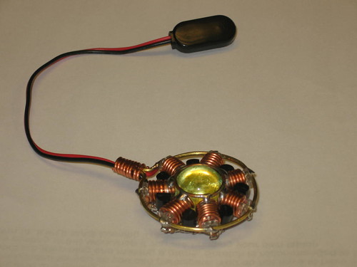
I have these available now for $75, shipping included, via Paypal. Email me at ellindsey@gmail.com for details.
Monday, May 17, 2010
An experimental servo modification holds up for the Steampunk World's Faire

After the gears, the next weak spot in the HX-12K servos is the case. I cracked several mounting tabs at GenCon last year. That problem seems to have gone away once I switched to larger rubber grommets around the mounting screws, and made sure all four screws were evenly tightened to spread the load. One servo cracked where I had installed a rear hinge point on the case, but that appears to have been an isolated case, probably due to assembly error on my part.
The main failure point now is the mounting of the axle shafts inside the gearbox. The gearbox main shaft is mounted by two ball bearings. I've yet to see that fail. The smaller hears inside the gearbox are located by two smaller shafts, which fit into plastic pockets in the gearbox housing. More expensive servos have brass bushings or even small ball bearings for the intermediate gear shafts, but the HX-12K and even the more expensive HS-5645MG servos have bare plastic there. I have seen on many servos, the HX-12K in particular, these mounting holes widened and even gouged out, allowing the middle gear in the servo to wobble back and forth. This lead to the geartrain coming unmeshed, locking solid, or even in one case a gear wandering into the side of the gearbox housing and gouging grooves in it.
As an experiment I took a few servo cases that were already trashed this way and carefully shaved out all remains of shaft mounting on the inside of the case. Then after carefully measuring an intact servo, I drilled and cut some .020 steel sheet to make locating plates to hold the top ends of the two intermediate shafts. Cutting and drilling by hand, it took several tries to make the locating plate precise enough for the gears to mesh properly and for the servo to run smoothly when reassembled. When the first servo I modified this way ran well during testing, I modified three more.
All four of the outer leg servos on the robot, the ones which raise and lower the leg segments, are now heavily modified hybrid models, having motors and control boards from HS-5645MG servos, the gears from HX-12K servos, and HX-12K cases modified with rear axle points and steel plates locating the intermediate gear shafts. The inner servos, which move the legs horizontally, don't seem to fail nearly as often, so I haven't modified them as much yet.
Sunday, March 28, 2010
Pendants are coming along, and mix-and-match servos
I have five more of the LED uranium-ball ring-circuit pendants finished and ready for sale. While my eventual goal is to have a dozen or so ready for the steampunk world's faire, I am aware that I had a backlog of people wanting theirs. Contact me if you were one of those.
I've been running the robot with HS-5645MG servos lately. I'm not happy with them. While they don't have the terrible problems with ringing and overshoot that the HX-12K servos had, they do have a weak gearbox design. The second-to-last gear in the gear chain is surprisingly thin. I've lost track of how many gears I've seen break on these servos, always in the exact same spot. The HX-12K servos had a much thicker gear in that same position, and I've never seen one fail that way. HX-12K servo failures I've seen tend to be electrical board or motor failures, or structural failures in the servo case.
I am experimenting with building a composite servos using the motors, potentiometers, and drive boards from the HS-5645MG servos and the gear train from the HX-12K servos. They have nearly the same gear ratio, and appear to have the same spacing between gears and same size shafting. There are some odd clearance issues. The HX-12K gears jam when installed in the HS-5645MG cases, although the HS-5645MG gears run fine in the HX-12K cases. I have installed the motors, drive boards, and potentiometer from a HS-5645MG in a HX-12K case with the HX-12K geartrain. The potentiometer is a tight fit and doesn't turn smoothly if I tighten the case screws tightly, but other than that the arrangement works.
The weak link is still the HX-12K case. The mounting tabs break off, the case itself cracks, and I've seen a few cases of total failure of the mounting boss for the small internal shafts inside the gearbox. Making my own cases from cast aluminum is out of the question in the condo, and having cases custom-machined would be unreasonably expensive. If I had that kind of budget, I would just buy higher-quality servos in the first place. Still looking for other options.
I've been running the robot with HS-5645MG servos lately. I'm not happy with them. While they don't have the terrible problems with ringing and overshoot that the HX-12K servos had, they do have a weak gearbox design. The second-to-last gear in the gear chain is surprisingly thin. I've lost track of how many gears I've seen break on these servos, always in the exact same spot. The HX-12K servos had a much thicker gear in that same position, and I've never seen one fail that way. HX-12K servo failures I've seen tend to be electrical board or motor failures, or structural failures in the servo case.
I am experimenting with building a composite servos using the motors, potentiometers, and drive boards from the HS-5645MG servos and the gear train from the HX-12K servos. They have nearly the same gear ratio, and appear to have the same spacing between gears and same size shafting. There are some odd clearance issues. The HX-12K gears jam when installed in the HS-5645MG cases, although the HS-5645MG gears run fine in the HX-12K cases. I have installed the motors, drive boards, and potentiometer from a HS-5645MG in a HX-12K case with the HX-12K geartrain. The potentiometer is a tight fit and doesn't turn smoothly if I tighten the case screws tightly, but other than that the arrangement works.
The weak link is still the HX-12K case. The mounting tabs break off, the case itself cracks, and I've seen a few cases of total failure of the mounting boss for the small internal shafts inside the gearbox. Making my own cases from cast aluminum is out of the question in the condo, and having cases custom-machined would be unreasonably expensive. If I had that kind of budget, I would just buy higher-quality servos in the first place. Still looking for other options.
Sunday, February 21, 2010
Exhibition at Wicked Faire
Yesterday I took the walking robot to the Wicked Winter Renaissance Faire to show off and entertain with. The trip was quite successful, with many fairgoers entertained. Unfortunately the problems I've been having with the HS5645MG gearboxes resurfaced. In this version I was running with hybrid servos containing the electronics, motors, and gears from HS5645MG servos installed in HX12K servo cases. HX12K cases were used simply because the ones I had were already fitted to the robot frame, and because I didn't have enough intact HS5645MG servo cases. HS5645MG servo innards were use because the HX12K servos had terrible position control and easily burned out motors.
Over the course of the day I had two gear failures. Both of them were identical to the failure I've seen before, with the second-to-last (counting from the motor) gear in the gear train losing teeth. This gear is surprisingly thin for the torque it's carrying. The same gear in the HX12K servo is significantly thicker, and in my robot has never failed.
I had spare gear sets on hand and was able to repair the damage and keep the robot going, but this is an unacceptable and expensive failure rate. I believe it may be possible to construct a hybrid servo using the gears from the HX12K and the motor and control board from the HS5645MG, which if it worked would give me the solid position control of the HS5645MG and the durability of the HX12K. Once the weather improves I will start working on that.
The other failure, which stopped my showing off the robot for the night, was when the antenna broke off the transmitter. The wire antenna that can come attached to the XBee radio module is made out of some very cheap and brittle coarse-stranded wire. I had long ago replaced the wire antenna on the receiver with a length of ultra-flexible wet noodle wire. Now I'll be doing the same with the transmitter.
I sold a few of the Uranium Ring Oscillator Pendants I've made at the faire, and had enough interest from people in them that I've set up an Etsy account. There's nothing much there now, but when I have some more jewelry made I'll be posting it there.
Over the course of the day I had two gear failures. Both of them were identical to the failure I've seen before, with the second-to-last (counting from the motor) gear in the gear train losing teeth. This gear is surprisingly thin for the torque it's carrying. The same gear in the HX12K servo is significantly thicker, and in my robot has never failed.
I had spare gear sets on hand and was able to repair the damage and keep the robot going, but this is an unacceptable and expensive failure rate. I believe it may be possible to construct a hybrid servo using the gears from the HX12K and the motor and control board from the HS5645MG, which if it worked would give me the solid position control of the HS5645MG and the durability of the HX12K. Once the weather improves I will start working on that.
The other failure, which stopped my showing off the robot for the night, was when the antenna broke off the transmitter. The wire antenna that can come attached to the XBee radio module is made out of some very cheap and brittle coarse-stranded wire. I had long ago replaced the wire antenna on the receiver with a length of ultra-flexible wet noodle wire. Now I'll be doing the same with the transmitter.
I sold a few of the Uranium Ring Oscillator Pendants I've made at the faire, and had enough interest from people in them that I've set up an Etsy account. There's nothing much there now, but when I have some more jewelry made I'll be posting it there.
Subscribe to:
Posts (Atom)