Showing posts with label arduino. Show all posts

Sunday, November 1, 2020

Halloween project: A safe non-contact automated candy dispensing device.

    Our neighborhood never has a large number of trick-or-treaters, even on a normal year, but I do always make a point of having candy on hand for the dozen or so kids that we get. This year, I wasn't certain we would get any at all, and I wasn't sure I'd feel safe handing out candy face-to-face with them if any did come by. I had for a while been planning to just shut the outside lights off and lock the door, but decided, a few weeks before holiday, that I could hand out candy in a safe, no-contact way after all.

    I saw how some people were setting up delivery tubes for safe remote candy delivery. I had a cardboard shipping tube on hand that I could use for that, but I realized that I could do better than just dropping candy in by hand. I designed a carousel mechanism based around a FIT0441 blushless gearmotor, which would have compartments for up to 10 loads of candy.


About a 28 hour long print on my printer, one of the largest single pieces I've ever printed.


Room for 10 loads of candy, although one will always be empty due to being over the dispending hole.

    A microswitch acts as a position sensor, telling the motor when to stop after rotating to release the next load of candy. The carousel mechanism was mounted at the top of the tube, so that candy would slide down the tube after being released.


Quick assembly of the mechanism.

    To control the system, I used some old Arduino Pro Mini clone boards left over from another project a few years back. I ran into a significant problem with these, as the power supplies on the board failed, and in once case literally exploded, as I tried to run them off the 12VDC power supply I had on hand. The Arduino Pro Mini has an on-board power regulator which is supposed to handle a 12VDC input, but every one of these boards failed when powered at 12V. This was especially surprising as I had powered these exact same boards off this exact power supply when I first bought them a few years ago. I can only assume that they somehow degraded while in storage, but I'm still baffled. Perhaps this is just a lesson that I should be using actual Arduino boards rather than cheap clones.

    I eventually resorted to desoldering the failing power supplies from the boards, and using an external 5V regulator to power them instead. This worked with one of the three boards I had on hand, the other two seemed to be completely dead.

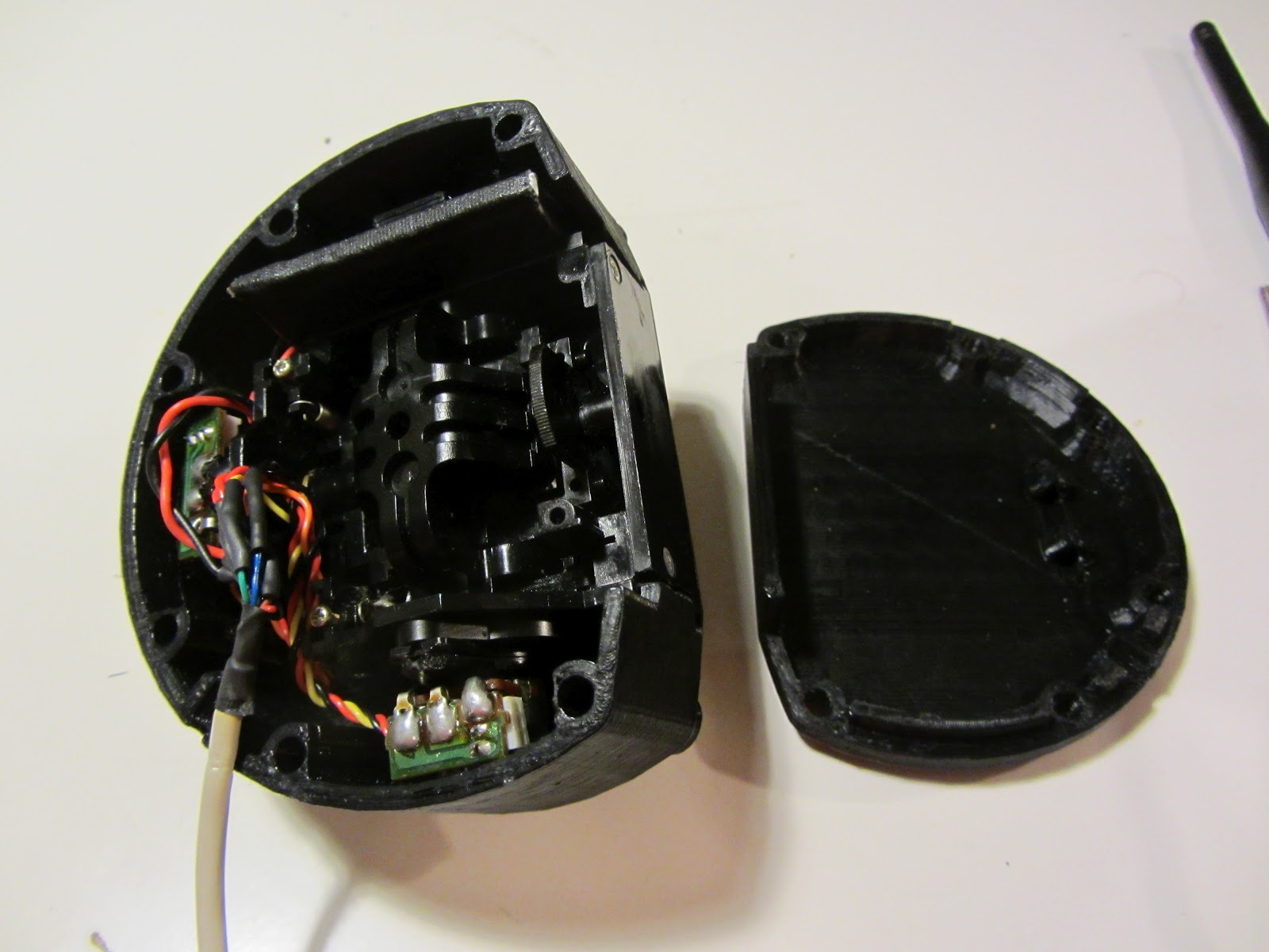
    At this point, it was getting fairly late on the day before Halloween, after spending a full day on getting the Arduino board to work, so the remaining wiring is a bit of a mess. Driving the motors was easy since the FIT0441 has a built-in motor control circuit. It has one wire for direction, and another which is used as a PWM speed control line. There's also a feedback line indicating motor rotation, but I didn't end up doing anything with that signal. Position control came from a big old microswitch out of my junk box which would be pressed to stop the motor after rotating.

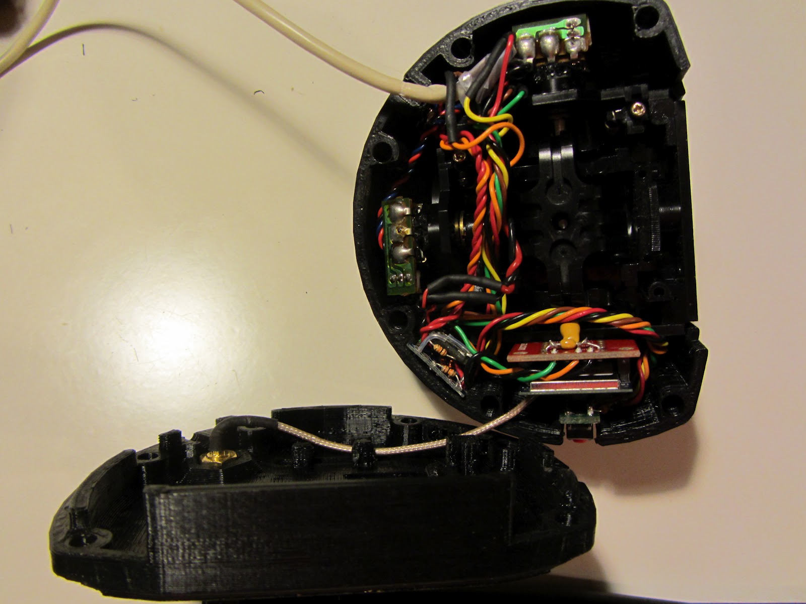
Somewhat messy wiring in the final assembly, but it worked. The motor is driving the carousel through an inside ring gear built into the underside of the carousel. I made spaces for three motors, but only one was needed.

    I could at this point have made the device dispense candy with a button push, but I wanted it to be truly non-contact, not requiring either the visiting kids or myself to have to touch anything. I had on hand an IR emitter/detector assembly from a broken hands-free paper towel dispenser. This was fairly easy to hook up to the Arduino Mini. The IR receiver this module was using to sense reflected light was originally designed for TV remote control use, and was only sensitive to light pulsed at 38khz. Getting the Arduino to output a 38khz signal requires my directly writing to the timer 2 registers, as there doesn't seem to be any clean way that I could find through the Arduino libraries. Once I figured out how to do that, it was easy to get the proximity detector to sense when someone was holding their hands, or a bag or basket, under the end of the tube.

Downward-facing IR LEDs and sensor on the board at the bottom. Big red LED at top.

    As a final touch, I added a blinking red LED to attract attention to the end of the tube. My wife drew up an instructional sign, and sacrificed one of her old pairs of tights to cover the tube and all the exposed wiring.

Finished candy dispenser.

    We ended up getting about half a dozen kids, in two groups. The dispenser worked well, and with some guidance from their parents and me calling out instructions from inside, all the kids were able to get candy from it. I did determine during testing that Twix bars would sometimes jam in the cartridges due to being just the right length to get caught diagonally, but once I pulled those out the mechanism worked well enough.

    This was a fun project for Halloween, built entirely with parts I had on hand. I'm not sure if I'll bother with something like this again next year, though if I do I'll probably redesign it from scratch, as the rotating carousel mechanism for dispensing candy was really crude and could be made a lot more reliable.

Monday, August 13, 2012

Little Walking Robot - Arduio Sketch

The software which runs on the Arduino in the transmitter is actually fairly simple.  The robot is essentially just a wireless puppet - movement of the joysticks is translated directly to movement of the legs.  All the fancy moves the robot does - walking, posing, waving at people, rolling over - is performed by the operator, moving the robot's joysticks and changing the mixing algorithm with the mode select buttons.  The software simply samples the mode buttons and analog inputs from the joysticks, performs some simple digital debouncing and filtering, calculates the desired position of each servo, and transmits the servo position commands out on the serial port.

In the robot,the serial output from the receiving XBee module is fed to the serial input of an 8-channel Pololu Serial Servo Controller.  The controller has some configuration settings that let you adjust the center points and ranges on each servo, but I'm bypassing those and setting the position directly with the Set Position, Absolute command.  I prefer to do those calculations in the transmitter.


int stickX = 0;
int stickY = 0;
int stickX2 = 0;
int stickY2 = 0;

long avgtemp = 0L;  //teprary long for digital filtering

//for all servos, 3000 is center

int servoFRX = 3000; 
int servoFLX = 3000; 
int servoRRX = 3000; 
int servoRLX = 3000; 
int servoFRY = 3000; 
int servoFLY = 3000; 
int servoRRY = 3000; 
int servoRLY = 3000; 

int outputFRX;
int outputFLX;
int outputRRX;
int outputRLX;
int outputFRY;
int outputFLY;
int outputRRY;
int outputRLY;

//trim the center points on each servo
//require because the MG996R servos are so damn inaccurate

#define trimFLY 0     //plus is ccw (down),        minus is cw (up)
#define trimFLX 0     //plus is ccw (back/left),   minus is cw (front/right)
#define trimRLY -100  //plus is ccw (down),        minus is cw (up)
#define trimRLX 0     //plus is ccw (back/right),  minus is cw (front/left)
#define trimRRX 30    //plus is ccw (front/right), minus is cw (back/left)
#define trimRRY 0     //plus is ccw (up),          minus is cw (down)
#define trimFRX -10   //plus is ccw (front/left),  minus is cw (back/right)
#define trimFRY 150   //plus is ccw (up),          minus is cw (down)

int mode = 0;  //miximg mode

byte button0 = 0;
byte button1 = 0;
byte button2 = 0;
byte button3 = 0;

byte button0oldstat = 0;
byte button1oldstat = 0;
byte button2oldstat = 0;
byte button3oldstat = 0;

byte buttoncount = 0;
byte invertmode = 0;

void setup()                    // run once, when the sketch starts
{
  ADMUX &= 0x3F;                // use 3.3V supply as AREF
  Serial.begin(38400);
 
  delay(500);  //give the radio time to start working
}

void loop()                     // run over and over again

  button0 = digitalRead(2);  //D2 - brown wire
  button1 = digitalRead(3);  //D3 - green wire
  button2 = digitalRead(4);  //D4 - yellow wire
  button3 = digitalRead(5);  //D5 - orange wire
 
  //check to see if the button inputs have changed
  //we use a timer variable for digital debouncing
 
  if (  (button0oldstat != button0)||
        (button1oldstat != button1)||
        (button2oldstat != button2)||
        (button3oldstat != button3)||
        ((button0 == 1)&&
         (button1 == 1)&&
         (button2 == 1)&&
         (button3 == 1))) {
      buttoncount = 0;
  }
  else {
    if (buttoncount == 20) {
      if ((button0 == 0)&&
         (button1 == 1)&&
         (button2 == 1)&&
         (button3 == 1)) {
           invertmode = 1 - invertmode;
      }
      else if (button0 == 1) {
             mode = (1 - button1) + (1 - button2) * 2 + (1 - button3) * 4;
         }
    }
    if (buttoncount < 21) {
      buttoncount = buttoncount + 1;
    }
  }
 
  button0oldstat = button0;
  button1oldstat = button1;
  button2oldstat = button2;
  button3oldstat = button3;
 
  //read analog inputs
  //we do some digital noise filtering here

  avgtemp = stickX * 3L + (analogRead(0) - 512) * 256L;  //A0 - right X - orange wire
  stickX = avgtemp / 4; // right joystick x

  avgtemp = stickY * 3L - (analogRead(1) - 512) * 256L;  //A1 - right Y - yellow wire
  stickY = avgtemp / 4; // right joystick y

  avgtemp = stickX2 * 3L + (analogRead(2) - 512) * 256L;  //A2 - left X - green wire
  stickX2 = avgtemp / 4; // left joystick x

  avgtemp = stickY2 * 3L + (analogRead(3) - 512) * 256L;  //A3 - left Y - brown wire
  stickY2 = avgtemp / 4; // left joystick y
 
  //determine the servo positions based on the joystick inputs
  //there is no sequencing here, it's all just direct one-to-one mapping of joystick inputs
  //to servo outputs, with the mode variable controlling which mixing algorithm to use.
 
  switch (mode) {
    case 1:  //basic walk algorithm
      servoFRY = 2000 - (stickY / 32);
      servoRRY = 2000 + (stickY / 32);
      servoFLY = 4000 - (stickY / 32);
      servoRLY = 4000 + (stickY / 32);
      servoFRX = 3000 - (stickX / 24) - (stickY2 / 30) - (stickX2 / 30);
      servoRRX = 3000 + (stickX / 24) + (stickY2 / 30) - (stickX2 / 30);
      servoFLX = 3000 + (stickX / 24) - (stickY2 / 30) + (stickX2 / 30);
      servoRLX = 3000 - (stickX / 24) + (stickY2 / 30) + (stickX2 / 30);
      break;
    case 2:  //wave front legs
      servoFRY = 2500 + (stickY / 16);
      servoFLY = 3500 + (stickY2 / 16);
      servoFRX = 3000 + (stickX / 24);
      servoFLX = 3000 + (stickX2 / 24);
      servoRRY = 2000;  //down
      servoRLY = 4000;  //down
      servoRLX = 4375;  //forward/left
      servoRRX = 1625;  //forward/right
      break;
    case 3:  //all servos center - used for alignment checks
      servoFRY = 3000;
      servoFLY = 3000;
      servoFRX = 3000;
      servoFLX = 3000;
      servoRRY = 3000;
      servoRLY = 3000;
      servoRRX = 3000;
      servoRLX = 3000;
      break;
    case 4:  //body lean/shift/dance
      servoFRY = 2000 + (stickY / 32) + (stickX / 32);
      servoRRY = 2000 - (stickY / 32) + (stickX / 32);
      servoFLY = 4000 - (stickY / 32) + (stickX / 32);
      servoRLY = 4000 + (stickY / 32) + (stickX / 32);
      servoFRX = 3000 + (stickY2 / 32) + (stickX2 / 32);
      servoRRX = 3000 + (stickY2 / 32) - (stickX2 / 32);
      servoFLX = 3000 - (stickY2 / 32) + (stickX2 / 32);
      servoRLX = 3000 - (stickY2 / 32) - (stickX2 / 32);
      break;
  }
 
  if (invertmode == 1) {  //inverted?
    outputRRY = servoRLY;
    outputRLY = servoRRY;
    outputFRY = servoFLY;
    outputFLY = servoFRY;
    outputRRX = servoRLX;
    outputRLX = servoRRX;
    outputFRX = servoFLX;
    outputFLX = servoFRX;
  }
  else {
    outputFRX = 6000 - servoFRX;
    outputFLX = 6000 - servoFLX;
    outputRRX = 6000 - servoRRX;
    outputRLX = 6000 - servoRLX;
    outputFRY = servoFRY;
    outputFLY = servoFLY;
    outputRRY = servoRRY;
    outputRLY = servoRLY;
  }
     
  //tweak nonzero servo centerpoints
 
  outputFRX = outputFRX + trimFRX;
  outputFLX = outputFLX + trimFLX;
  outputRRX = outputRRX + trimRRX;
  outputRLX = outputRLX + trimRLX;
  outputFRY = outputFRY + trimFRY;
  outputFLY = outputFLY + trimFLY;
  outputRRY = outputRRY + trimRRY;
  outputRLY = outputRLY + trimRLY;
 
  //constrain to actual servo travel limits
 
  outputFRY = constrain(outputFRY,1000,5000);
  outputRRY = constrain(outputRRY,1000,5000);
  outputFLY = constrain(outputFLY,1000,5000);
  outputRLY = constrain(outputRLY,1000,5000);
  outputFRX = constrain(outputFRX,1000,5000);
  outputRRX = constrain(outputRRX,1000,5000);
  outputFLX = constrain(outputFLX,1000,5000);
  outputRLX = constrain(outputRLX,1000,5000);
 
  //transmit to robot
 
  Serial.write((byte)0x80);
  Serial.write((byte)0x01);
  Serial.write((byte)0x04);
  Serial.write((byte)0x00);
  Serial.write((byte)(outputFRY / 128));
  Serial.write((byte)(outputFRY % 128));
 
  Serial.write((byte)0x80);
  Serial.write((byte)0x01);
  Serial.write((byte)0x04);
  Serial.write((byte)0x01);
  Serial.write((byte)(outputFRX / 128));
  Serial.write((byte)(outputFRX % 128));
 
  Serial.write((byte)0x80);
  Serial.write((byte)0x01);
  Serial.write((byte)0x04);
  Serial.write((byte)0x02);
  Serial.write((byte)(outputRRY / 128));
  Serial.write((byte)(outputRRY % 128));
 
  Serial.write((byte)0x80);
  Serial.write((byte)0x01);
  Serial.write((byte)0x04);
  Serial.write((byte)0x03);
  Serial.write((byte)(outputRRX / 128));
  Serial.write((byte)(outputRRX % 128));
 
  Serial.write((byte)0x80);
  Serial.write((byte)0x01);
  Serial.write((byte)0x04);
  Serial.write((byte)0x04);
  Serial.write((byte)(outputRLX / 128));
  Serial.write((byte)(outputRLX % 128));
 
  Serial.write((byte)0x80);
  Serial.write((byte)0x01);
  Serial.write((byte)0x04);
  Serial.write((byte)0x05);
  Serial.write((byte)(outputRLY / 128));
  Serial.write((byte)(outputRLY % 128));
 
  Serial.write((byte)0x80);
  Serial.write((byte)0x01);
  Serial.write((byte)0x04);
  Serial.write((byte)0x06);
  Serial.write((byte)(outputFLX / 128));
  Serial.write((byte)(outputFLX % 128));
 
  Serial.write((byte)0x80);
  Serial.write((byte)0x01);
  Serial.write((byte)0x04);
  Serial.write((byte)0x07);
  Serial.write((byte)(outputFLY / 128));
  Serial.write((byte)(outputFLY % 128));
 
}

Sunday, August 12, 2012

Little Walking Robot: Controller Rebuild


 The little walking robot is getting a rebuild in preparation for GenCon 2012 - only days away as I write this.  I haven't actually changed much on the robot itself.  It worked well at last year's convention, so the main changes I made to it were to replace broken parts.  The big change I've made this year is completely rebuilding the transmitter.

Last year's transmitter was built around a FunnelIO board.  This is an Arduino clone with a socket for a XBee radio module and a USB-powered LiPoly battery charger on the board.  This was nearly everything needed for the transmitter function on one board, and it worked well for that version of the transmitter.  What I didn't like about the FunnelIO was the size.  It was too large to fit cleanly in the transmitter cases I built, sticking out one side awkwardly.  It was also awkward to program.  The USB port on the FunnelIO was only usable for battery charging.  To program the controller, I needed to remove the XBee module and plug in a FTDI serial converter with a handmade adapter cable.

The redesign started with Sparkfun's Free Day 2012, back in January.  The previous two years I'd been unable to win anything through it.  This year I was persistent and lucky, and managed to get among other parts three parts for a new robot controller:  an Arduino Pro Mini, an Xbee breakout board, and a Li-poly battery charger.  These three parts, along with the Xbee module I already had, would make the core of a new controller.


 One goal I had for the new controller was to be able to program it without disassembling it, through the same USB port used to charge the controller battery.  This would be challenging, both mechanically and electrically.  I had a FTDI UBS-to-serial converter board I'd been using for programming in the past, but it had the wrong connector type, a type A (computer side) plug, rather than the mini-B I'd like to use.  The battery charger board had a mini-B connector, but no easy access to the data pins.  I ended up removing the type A connector from the FTDI board, then  very carefully soldering tiny wire-wrapping wires onto the mini-B connector on the battery charger, and running them to the pads where the connector on the USB-to-serial converter board had been.

Now I had a single port that would simultaneously connect both the battery charger and the USB-to-serial converter.  Now the challenge was the electrical integration.  The Arduino board only has a single serial port which is used for both programming and to transmit data to the XBee module. I needed to be able to program the board through this port while it was connected to my laptop, and then have it work normally as a transmitter, the two functions not interfering with each other, without having to plug or unplug modules.  I also needed to be able to plug the transmitter into my laptop with the Arduino and XBee powered off so I could just leave the battery to charge.

I ended up connecting the USB-to-serial board to the Arduino pro with a rats-nest of resistors and diodes.  When the USB connector is unplugged, the battery charger and serial converter board are unpowered.  The diode on the Arduino TXD line prevents the shut-down converter board from interfering with the communications between the Arduino and the XBee module.  When the USB connector is plugged in, the USB-to-serial converter board can drive the serial and reset lines as needed to program the Arduino.  And when the transmitter is switched off, only the battery charger and serial converter are powered by the USB connection, with the diode on the arduino RXD line preventing the Arduino from being possibly damaged by having its serial input driven while the board is unpowered.

The three boards - the Arduino Pro Mini, the USB-to-serial converter, and the USB battery charger - are tightly sandwiched together.  I didn't get a good picture of that assembly, but it's hard to see what's going on anyway.  The following schematic shows the connections, as well as how the joysticks and mode select buttons are connected.


Many of the parts are recycled from the previous version of the controller.  The joysticks are the same old RC airplane controller sticks, and the mode select buttons are the same pushbuttons on a PCB assembly.  I'm also still using the same grossly over-powered 1000mAh lipoly battery.

Since the start of this year I've had access to a 3D printer at work.  I wasn't initially confident enough in the strength of the printed parts to use them for the robot, but I decided to see if I could make a new transmitter housing, something to replace the old plywood frame I'd been using.  The big advantage of the 3Dprinted housing was the ability to make it in any arbitrary shape.  I decided to keep the overall outline the same as I had with the plywood housing, but was able to design pockets and channels internally to hold all the components and wires.


The basic form would be the same as the last one, with right-hand and left-hand controllers connected by a cable.  Each controller would be made up of two pieces, a larger 'front' piece that held the joysticks and most of the components, and a mostly-flat 'rear' panel.  Here's one of the rear panels being printed.  These parts are big, near the maximum size that could fit on the Makerbot Thing-O-Matic build platform.


A test-fit of the rear panel of the right-hand controller.  The Xbee radio module fits into a slot, with a channel to route the antenna wire to the antenna connector set into the back.  I was also experimenting with a smaller battery, shown here, but ended up going with the larger battery I'd used in previous years instead.


The completed left-hand controller!  The RC airplane joystick fits flush into the front-side housing.  You can see the to center adjust trims sticking out through the front face as well.  I ended up attaching guards around these to make it impossible to knock them out of position by accident.


The left-hand controller, opened up.  The joystick assembly occupies nearly the entire interior.  There's just enough room for the battery, which is the black oblong object above the joystick.


The right-hand controller has a bit more going on.  The four mode-control buttons are placed where I can easily press them with my fingers while working the joystick with my thumb.  The USB charging/programming port is visible, right above the Arduino reset button.  This side also has the radio transmitter and antenna, and the main power switch.


The right side controller opened up.  It's a bit hard to see what's going on - the modules are fairly tightly installed and obscured by wiring.  As with the left-hand controller, the joystick takes up most of the interior.  The Xbee radio module is at the bottom of the controller in this photo, and the Arduino/battery charger/serial converter assembly is just to the left of it.


Closeup on the control boards.  XBee carrier is on the left, with the wiring bundle to the mode select buttons snaking around it.  The Tantalum capacitor soldered across the XBee power terminals seems to be vital, I couldn't keep a reliable radio link without it.  The barely-visible control board is to the right.


Viewed from the opposite angle.  You can see the mode select buttons to the right, and the controller module to the left.  Admittedly it's hard to see how they're connected in this shot. The schematic posted above should make it clear.


All buttoned up, and ready to go to the convention!

On the robot itself, the biggest change has been replacing some of the steel parts of all four legs with printed parts.


After building the transmitter case, and some other test parts, I was confident enough in the strength of the 3D-printed parts to use them for the leg structure.  They seem to be holding up so far.  We'll see if any break over the convention weekend.