After blowing up my old PC power supply, I ordered a 360W, 12V industrial supply off Ebay. Two days later it arrived and went right into the printer.
It's got a larger footprint than the older one, but still fits in the printer base.
While waiting for the new supply to arrive I tool apart the old one and removed what usable parts from it I could. I took the entire back plate, with the AC plug, switch, and fan, and mounted it on one side of the printer to give me a convenient power switch and plug. I took the other fan and aimed it to cool the RAMPS board. Other than the power input, none of this is securely mounted yet - something I'll have to do eventually.
The new power supply doesn't have a secondary 5V output, and I didn't want to run the print head fans and LEDs off the RAMPS board's 5V line, so I threw together a deadbug 5V supply with a 7805 regulator and a few capacitors. This is mounted to the underside of the upper structural plate, out of the way of the moving parts of the print head. I'll eventually be installing some more LEDs up there as well to illuminate the entire print area.
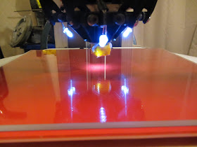
The print surface is a standard 200mm heated bed from Lulzbot. I'm mounting it on springs on each corner so it will have some give if the head crashes into the bed, and to give me a way to fine-adjust the bed level. The bed is mounted to a plywood plate that is itself attached to the three motor mount blocks at the corners of the printer. Not shown here is the borosilicate glass plate that goes on top of the bed.
Eventually I intend to put some insulation under and around the print bed to make it a bit easier to keep it at the target temperature, and some LEDs to indicate when the heater is operating. What I'd really like to do is have a ring of red LEDs around the bed which are on whenever the bed is over a certain temperature, but I suspect that will require me to modify the printer firmware.
Now the print area of the Rostock design isn't actually a perfect match to the square print bed. The actual physical area the head can move through is a sort of rounded hexagon shape, but it's fairly close to being a circle about nine and a half inches in diameter. Ideally, the printer should have a circular print bed. I haven't seen any circular print beds on sale yet, but if the Rostock design becomes popular they might appear. I might also design and etch my own at some point. I'll need to find a source for a circular glass print surface too.
The LEDs on the print head are adjusted to illuminate the area directly under the J-head nozzle. This will help with aligning the head to the center of the print area (though admittedly this is much less of an issue with this design than it was with the Makerbot) and with testing the extruder function.
Everything has been hooked up and electrically tested. I've run the print head and heated bed up to operating temperature and manually commanded the head to move through its entire operating volume. The new power supply shows no signs of failure under full load. It is getting to be a bit of a rat's nest in there, so at some point I'm going to have to work out better wire management and mounting. At least none of the parts in the base move, so I won't need to make cable chains like I had to for the office Makerbot.
The next step will be to build the pinch-wheel filament drive. For that, I'll need to print out a few more pieces on the office Makerbot. Once that is done and my PLA reels arrive, I'll be able to start printing.


Nice build. I think a bigger one like this will be my next project. I must admit that I'm almost done with one project, just started another and about to start a large rostock build.
ReplyDelete