Showing posts with label little walking robot. Show all posts

Tuesday, August 26, 2014

Building the new robot for GenCon 2014

My little walking robot, that this blog was originally created to describe, gradually beat itself to death through performing at conventions and Makerfaires over a period of several years.  Broken servos were easy (if expensive) to replace, but eventually welds cracked in the legs and the servo control board developed intermittent faults.  Fixes to the structural problems just made it heavier and pushed the already overloaded servos further.  About a year ago I gave up and declared it dead.

Earlier this year I decided to rebuild a new walking robot from scratch.  I had at one point looked at tiny inexpensive plastic-geared micro servos as a possibility for a walking robot.  Initially I thought them too weak and small for use in any walking robot, but after seeing several successful robots using them I decided to try and rebuild my walking robot based around them.


I knew from my earlier experimenting that these micro servos would burn out if I ran them at 6V like I had in the earlier robot.  Rather than drop the 8V from a two-cell LiPoly down to 5V or lower, I decided to just run the servos directly off a single cell LiPoly instead.  4V is less than the maximum these servos should be run at, but I figured that it would help them last longer without overheating.  I wasn’t going to be getting much torque out of them, so I’d need to make the robot as lightweight and small as possible.


I made as much of the structure as possible out of 3D-printed parts.  My original justification for getting the 3D printer was to print parts for robots.  I spent a few years making homemade transformers and other fun things instead, but now I’d finally be getting to making robot parts.  The printer was really great for this job, the fact that I could make parts in complex arbitrary shapes, compound curves which would be very difficult to make with sheet metal and internal stiffening ribs without welding or machining, really helped with my goal of making the bot with as few overall parts and fasteners as possible.  


Thanks to the 3D printer I was quickly able to go through multiple sets of test hardware, tweaking the design to get the clearances and geometry just right. It also meant I could fairly easily make an entire set of spare structural parts.  I didn’t expect to need them, but once I had the design finished it cost very little in materials or time to print more out.


I kept the same overall proportions as the previous robot, but scaled down everything by about five-eighths compared to the original.  I wanted to try and make the legs as short as I could get away with, reducing the torque load on the servos while still keeping the legs long enough for decent speed and mobility.  The center sphere, which in the original had been made from a three-inch copper tank float, would now be a plastic ball about two inches in diameter.  The leg span at full extension would be just about eleven inches.  I expected to be able to reduce the weight to about a quarter of the previous design. 

Sadly the printed plastic parts don’t quite have the aesthetic charm that the old polished metal ones did.  My robot’s gone from a steampunk inspired hand-made design to one that looks more like a mass-produced toy.  The final colors were somewhat accidental - I had a different color scheme in mind originally.  I printed out some test pieces in white, then switched to red and yellow, colors I don’t use much outside of test prints.  I liked the resulting look enough to make the entire robot in those colors.


I decided to switch to easily replaceable battery packs rather than attempt to cram in a single battery capable of running for an entire convention.  I got a really good deal on five single-cell 380mAh battery that would just fit inside the two-inch sphere, with enough space left over for the radio receiver. Of course, I added battery protection boards onto each of them to make sure that the robot wouldn’t go up flames in case of a short circuit.  I designed a printed shroud to go around the battery which I hoped would make it easy to swap out batteries without needing tools at the convention.  Unfortunately the plastic snaps came out stiffer than I'd have liked, and I needed to use pliers to pull the battery out at the convention.  It was still reasonably easy to swap the battery packs out.


With the battery pack and the Xbee radio taking up nearly all the space inside the robot, there wasn’t enough room for the Xbee breakout board I had used previously, let alone that and a Pololu SSC or Arduino Mini to do the serial-to-servo conversion.  I had to make my own controller board, using tiny right-angle headers mounted sideways on the board and fitting the PCB itself directly between the pin headers on the Xbee radio.  The board would have to hold a PIC16LF873A microcontroller, 3.3V regulator for the MCU and radio, clock generator and other required components, as well as the connectors for the battery and servos.  The servo leads and connectors actually took up a lot of the interior space - when you only have a 2 inch sphere to work with, trying to fit 8 3-pin headers takes up a painfully large chunk of the available real estate.

I designed the PCB using the layout tools I have available at work, and then ordered it through OSH Park.  OSH Park was quite easy to work with and helped me configure my PCB design software to produce the right output files for their process.  The cost for the three boards they sent me was amazingly low compared with other prototyping services, only $9 for three identical boards which was even less than it would have cost me to set up to etch them at home.  The quality was a lot better than I’ve ever been able to do with etching myself too.  They also had no problems with the boards being odd, non-rectangular shapes, unlike most prototyping services that require rectangles of predetermined sizes.  The only downside to OSH Park’s service is that it’s not speedy, the batch-process system they use to keep costs down means they have to wait until they get enough orders before they can send boards to be manufactured.


The radio receiver, controller board, battery, and connectors occupy a box about an inch square down the center of the two inch sphere center body.  It's really tightly packed in there.  I had to make cutouts in the PCB and battery support structure for the inner mounting tabs of the leg servos, and leave channels in the surrounding support structure wide enough to feed the servo leads through.


The firmware I wrote for the controller in the robot is really simple.  It’s essentially doing the same job as the Pololu SSC I used previously, but with a simpler protocol, lower data rate, and coarser resolution.  The receiver takes a data stream at 8929 baud (it was supposed to be 9600 baud, but a PIC16LF873A running off a 4mhz crystal can’t actually match a 9600 baud rate) with each servo encoded as a single byte of data, and outputs eight 0.524ms to 2.500ms pulses, one for each servo.  The output resolution is fairly coarse (about 0.7 degrees per LSB) but I figure that these cheap all-plastic servos are going to be lucky to be within five degrees of the commanded position anyway so it really doesn’t matter.

I used the same transmitter as on the previous version of the robot.  The only change I made was for the new serial output format for talking to my controller instead of the Pololu SSC board.  I did have some problems with the transmitter at the convention, and I’ll probably be completely redesigning it for next year.

The controller board was the long pole in the project, once it was done and programmed everything came together quickly.  There were a few design issues with the board that I had to fix with cutting traces and soldering additional parts on. For one thing, the Xbee receiver uses a lot more current than I realized, requiring me to solder a larger 3.3V regulator on.  I’ll be updating the PCB files and publishing them once I’ve cleaned up the design.

With these cheap little servos, and my previous experiences with them failing after a few seconds of running under load, I wasn’t sure that this robot would even be able to hold up its own weight without breaking.  I was therefore pleasantly surprised when the new robot not only stood but nimbly walked around, waved and rolled over just as well as the old one had.  Some quick testing showed that a single fully charged battery would be good for fifteen minutes of solid walking, and that I was able to go through several full batteries walking the robot around my living room without any servo failures.  Testing at work showed that the radio range was more than sufficient for the robot to still walk while at the other end of the longest hallway in the building, something that I had been worried about as there was no room for any kind of external antenna on the robot.


With everything tested and seeming to work, I packed the robot and all its spare parts and was off to GenCon.

Monday, August 4, 2014

Adding a second hinge point to cheap micro servos

Several years ago when looking for cheap servos to use for my walking robot I purchased a handful of HXT900 micro servos from HobbyKing.  They seemed like an incredible deal for less than $3 each, but after brief experimenting I gave up on them.  They were very jittery, not terribly strong, and when run at 6V the motor would burn out quickly if the output was stalled.  I tossed them in the junk box and forgot about them, writing them off as not usable for my robots.

Later, at Makerfaire NYC I talked to a maker who was developing kits for a hexapod robot that used 18 HXT900 servos, who had been having some success getting them to work.  I also some very impressive projects online of robots based on these servos, which was enough to make me reconsider my first impression.  My old quadruped walking robot was completely wrecked from many weekends of running demos, so I decided to build a completely new one from scratch based around the HXT900 servos.

The first thing I needed to do with these servos was add a second hinge point to them.  The knee design my robot has uses the servo case as half the hinge joint.  I'm using the same design as on the previous robot, but scaled down, using a 4-40 weld nut, 1/4" OD spacer, and 4-40 machine screw for each servo.


The first thing that needs to be done is completely removing all the stickers from the outside of each servo.  They'll prevent you from opening the case, and the tolerances on my design were tight enough that the stickers were being damaged when I installed the servos into the prototype chassis anyway.


The hole for the rear axle needs to be directly opposite the output shaft.  In theory I should have made up a jig for this, but just eyeballing it seemed to be close enough.  The hole doesn't precisely locate the axle point anyway, so it only needs to be approximate.


For plastic this thin, a drill bit would be overkill, and would probably risk shattering the case.  I used a good sharp Exacto knife to carve out the hole.  Again, the diameter of the hole is not critical, it just needs to be large enough to clear the barrel on the weld nut.


 Then glue a weld nut to the inside of each servo case.  The weld nuts I used just barely fit inside the rear of the servo case.  This helped with alignment - the sides of the servo case held the nut in place, so the position of the hole in the case didn't really matter so much.  You'll also want to make sure to remove any inspection sticker or other residue from the inside of the case before this step so the glue bonds effectively.


The spacer and screw are then temporarily put on to help clamp the weld nut against the inside of the case while the glue sets.  I'll be having to remove them later to install the servo in the knee joint.


 Finally here are two of the servos (pre-modification) installed in a test prototype for the new 3D-printed knee joint, next tot he same structure on the old robot.  You can see that the new design will be much smaller and lighter weight.  I'll also be taking a lot of advantage of the 3D printer's ability to make complex arbitrary shapes for the new robot's structure.

Monday, August 13, 2012

Little Walking Robot - Arduio Sketch

The software which runs on the Arduino in the transmitter is actually fairly simple.  The robot is essentially just a wireless puppet - movement of the joysticks is translated directly to movement of the legs.  All the fancy moves the robot does - walking, posing, waving at people, rolling over - is performed by the operator, moving the robot's joysticks and changing the mixing algorithm with the mode select buttons.  The software simply samples the mode buttons and analog inputs from the joysticks, performs some simple digital debouncing and filtering, calculates the desired position of each servo, and transmits the servo position commands out on the serial port.

In the robot,the serial output from the receiving XBee module is fed to the serial input of an 8-channel Pololu Serial Servo Controller.  The controller has some configuration settings that let you adjust the center points and ranges on each servo, but I'm bypassing those and setting the position directly with the Set Position, Absolute command.  I prefer to do those calculations in the transmitter.


int stickX = 0;
int stickY = 0;
int stickX2 = 0;
int stickY2 = 0;

long avgtemp = 0L;  //teprary long for digital filtering

//for all servos, 3000 is center

int servoFRX = 3000; 
int servoFLX = 3000; 
int servoRRX = 3000; 
int servoRLX = 3000; 
int servoFRY = 3000; 
int servoFLY = 3000; 
int servoRRY = 3000; 
int servoRLY = 3000; 

int outputFRX;
int outputFLX;
int outputRRX;
int outputRLX;
int outputFRY;
int outputFLY;
int outputRRY;
int outputRLY;

//trim the center points on each servo
//require because the MG996R servos are so damn inaccurate

#define trimFLY 0     //plus is ccw (down),        minus is cw (up)
#define trimFLX 0     //plus is ccw (back/left),   minus is cw (front/right)
#define trimRLY -100  //plus is ccw (down),        minus is cw (up)
#define trimRLX 0     //plus is ccw (back/right),  minus is cw (front/left)
#define trimRRX 30    //plus is ccw (front/right), minus is cw (back/left)
#define trimRRY 0     //plus is ccw (up),          minus is cw (down)
#define trimFRX -10   //plus is ccw (front/left),  minus is cw (back/right)
#define trimFRY 150   //plus is ccw (up),          minus is cw (down)

int mode = 0;  //miximg mode

byte button0 = 0;
byte button1 = 0;
byte button2 = 0;
byte button3 = 0;

byte button0oldstat = 0;
byte button1oldstat = 0;
byte button2oldstat = 0;
byte button3oldstat = 0;

byte buttoncount = 0;
byte invertmode = 0;

void setup()                    // run once, when the sketch starts
{
  ADMUX &= 0x3F;                // use 3.3V supply as AREF
  Serial.begin(38400);
 
  delay(500);  //give the radio time to start working
}

void loop()                     // run over and over again

  button0 = digitalRead(2);  //D2 - brown wire
  button1 = digitalRead(3);  //D3 - green wire
  button2 = digitalRead(4);  //D4 - yellow wire
  button3 = digitalRead(5);  //D5 - orange wire
 
  //check to see if the button inputs have changed
  //we use a timer variable for digital debouncing
 
  if (  (button0oldstat != button0)||
        (button1oldstat != button1)||
        (button2oldstat != button2)||
        (button3oldstat != button3)||
        ((button0 == 1)&&
         (button1 == 1)&&
         (button2 == 1)&&
         (button3 == 1))) {
      buttoncount = 0;
  }
  else {
    if (buttoncount == 20) {
      if ((button0 == 0)&&
         (button1 == 1)&&
         (button2 == 1)&&
         (button3 == 1)) {
           invertmode = 1 - invertmode;
      }
      else if (button0 == 1) {
             mode = (1 - button1) + (1 - button2) * 2 + (1 - button3) * 4;
         }
    }
    if (buttoncount < 21) {
      buttoncount = buttoncount + 1;
    }
  }
 
  button0oldstat = button0;
  button1oldstat = button1;
  button2oldstat = button2;
  button3oldstat = button3;
 
  //read analog inputs
  //we do some digital noise filtering here

  avgtemp = stickX * 3L + (analogRead(0) - 512) * 256L;  //A0 - right X - orange wire
  stickX = avgtemp / 4; // right joystick x

  avgtemp = stickY * 3L - (analogRead(1) - 512) * 256L;  //A1 - right Y - yellow wire
  stickY = avgtemp / 4; // right joystick y

  avgtemp = stickX2 * 3L + (analogRead(2) - 512) * 256L;  //A2 - left X - green wire
  stickX2 = avgtemp / 4; // left joystick x

  avgtemp = stickY2 * 3L + (analogRead(3) - 512) * 256L;  //A3 - left Y - brown wire
  stickY2 = avgtemp / 4; // left joystick y
 
  //determine the servo positions based on the joystick inputs
  //there is no sequencing here, it's all just direct one-to-one mapping of joystick inputs
  //to servo outputs, with the mode variable controlling which mixing algorithm to use.
 
  switch (mode) {
    case 1:  //basic walk algorithm
      servoFRY = 2000 - (stickY / 32);
      servoRRY = 2000 + (stickY / 32);
      servoFLY = 4000 - (stickY / 32);
      servoRLY = 4000 + (stickY / 32);
      servoFRX = 3000 - (stickX / 24) - (stickY2 / 30) - (stickX2 / 30);
      servoRRX = 3000 + (stickX / 24) + (stickY2 / 30) - (stickX2 / 30);
      servoFLX = 3000 + (stickX / 24) - (stickY2 / 30) + (stickX2 / 30);
      servoRLX = 3000 - (stickX / 24) + (stickY2 / 30) + (stickX2 / 30);
      break;
    case 2:  //wave front legs
      servoFRY = 2500 + (stickY / 16);
      servoFLY = 3500 + (stickY2 / 16);
      servoFRX = 3000 + (stickX / 24);
      servoFLX = 3000 + (stickX2 / 24);
      servoRRY = 2000;  //down
      servoRLY = 4000;  //down
      servoRLX = 4375;  //forward/left
      servoRRX = 1625;  //forward/right
      break;
    case 3:  //all servos center - used for alignment checks
      servoFRY = 3000;
      servoFLY = 3000;
      servoFRX = 3000;
      servoFLX = 3000;
      servoRRY = 3000;
      servoRLY = 3000;
      servoRRX = 3000;
      servoRLX = 3000;
      break;
    case 4:  //body lean/shift/dance
      servoFRY = 2000 + (stickY / 32) + (stickX / 32);
      servoRRY = 2000 - (stickY / 32) + (stickX / 32);
      servoFLY = 4000 - (stickY / 32) + (stickX / 32);
      servoRLY = 4000 + (stickY / 32) + (stickX / 32);
      servoFRX = 3000 + (stickY2 / 32) + (stickX2 / 32);
      servoRRX = 3000 + (stickY2 / 32) - (stickX2 / 32);
      servoFLX = 3000 - (stickY2 / 32) + (stickX2 / 32);
      servoRLX = 3000 - (stickY2 / 32) - (stickX2 / 32);
      break;
  }
 
  if (invertmode == 1) {  //inverted?
    outputRRY = servoRLY;
    outputRLY = servoRRY;
    outputFRY = servoFLY;
    outputFLY = servoFRY;
    outputRRX = servoRLX;
    outputRLX = servoRRX;
    outputFRX = servoFLX;
    outputFLX = servoFRX;
  }
  else {
    outputFRX = 6000 - servoFRX;
    outputFLX = 6000 - servoFLX;
    outputRRX = 6000 - servoRRX;
    outputRLX = 6000 - servoRLX;
    outputFRY = servoFRY;
    outputFLY = servoFLY;
    outputRRY = servoRRY;
    outputRLY = servoRLY;
  }
     
  //tweak nonzero servo centerpoints
 
  outputFRX = outputFRX + trimFRX;
  outputFLX = outputFLX + trimFLX;
  outputRRX = outputRRX + trimRRX;
  outputRLX = outputRLX + trimRLX;
  outputFRY = outputFRY + trimFRY;
  outputFLY = outputFLY + trimFLY;
  outputRRY = outputRRY + trimRRY;
  outputRLY = outputRLY + trimRLY;
 
  //constrain to actual servo travel limits
 
  outputFRY = constrain(outputFRY,1000,5000);
  outputRRY = constrain(outputRRY,1000,5000);
  outputFLY = constrain(outputFLY,1000,5000);
  outputRLY = constrain(outputRLY,1000,5000);
  outputFRX = constrain(outputFRX,1000,5000);
  outputRRX = constrain(outputRRX,1000,5000);
  outputFLX = constrain(outputFLX,1000,5000);
  outputRLX = constrain(outputRLX,1000,5000);
 
  //transmit to robot
 
  Serial.write((byte)0x80);
  Serial.write((byte)0x01);
  Serial.write((byte)0x04);
  Serial.write((byte)0x00);
  Serial.write((byte)(outputFRY / 128));
  Serial.write((byte)(outputFRY % 128));
 
  Serial.write((byte)0x80);
  Serial.write((byte)0x01);
  Serial.write((byte)0x04);
  Serial.write((byte)0x01);
  Serial.write((byte)(outputFRX / 128));
  Serial.write((byte)(outputFRX % 128));
 
  Serial.write((byte)0x80);
  Serial.write((byte)0x01);
  Serial.write((byte)0x04);
  Serial.write((byte)0x02);
  Serial.write((byte)(outputRRY / 128));
  Serial.write((byte)(outputRRY % 128));
 
  Serial.write((byte)0x80);
  Serial.write((byte)0x01);
  Serial.write((byte)0x04);
  Serial.write((byte)0x03);
  Serial.write((byte)(outputRRX / 128));
  Serial.write((byte)(outputRRX % 128));
 
  Serial.write((byte)0x80);
  Serial.write((byte)0x01);
  Serial.write((byte)0x04);
  Serial.write((byte)0x04);
  Serial.write((byte)(outputRLX / 128));
  Serial.write((byte)(outputRLX % 128));
 
  Serial.write((byte)0x80);
  Serial.write((byte)0x01);
  Serial.write((byte)0x04);
  Serial.write((byte)0x05);
  Serial.write((byte)(outputRLY / 128));
  Serial.write((byte)(outputRLY % 128));
 
  Serial.write((byte)0x80);
  Serial.write((byte)0x01);
  Serial.write((byte)0x04);
  Serial.write((byte)0x06);
  Serial.write((byte)(outputFLX / 128));
  Serial.write((byte)(outputFLX % 128));
 
  Serial.write((byte)0x80);
  Serial.write((byte)0x01);
  Serial.write((byte)0x04);
  Serial.write((byte)0x07);
  Serial.write((byte)(outputFLY / 128));
  Serial.write((byte)(outputFLY % 128));
 
}

Sunday, August 12, 2012

Little Walking Robot: Controller Rebuild


 The little walking robot is getting a rebuild in preparation for GenCon 2012 - only days away as I write this.  I haven't actually changed much on the robot itself.  It worked well at last year's convention, so the main changes I made to it were to replace broken parts.  The big change I've made this year is completely rebuilding the transmitter.

Last year's transmitter was built around a FunnelIO board.  This is an Arduino clone with a socket for a XBee radio module and a USB-powered LiPoly battery charger on the board.  This was nearly everything needed for the transmitter function on one board, and it worked well for that version of the transmitter.  What I didn't like about the FunnelIO was the size.  It was too large to fit cleanly in the transmitter cases I built, sticking out one side awkwardly.  It was also awkward to program.  The USB port on the FunnelIO was only usable for battery charging.  To program the controller, I needed to remove the XBee module and plug in a FTDI serial converter with a handmade adapter cable.

The redesign started with Sparkfun's Free Day 2012, back in January.  The previous two years I'd been unable to win anything through it.  This year I was persistent and lucky, and managed to get among other parts three parts for a new robot controller:  an Arduino Pro Mini, an Xbee breakout board, and a Li-poly battery charger.  These three parts, along with the Xbee module I already had, would make the core of a new controller.


 One goal I had for the new controller was to be able to program it without disassembling it, through the same USB port used to charge the controller battery.  This would be challenging, both mechanically and electrically.  I had a FTDI UBS-to-serial converter board I'd been using for programming in the past, but it had the wrong connector type, a type A (computer side) plug, rather than the mini-B I'd like to use.  The battery charger board had a mini-B connector, but no easy access to the data pins.  I ended up removing the type A connector from the FTDI board, then  very carefully soldering tiny wire-wrapping wires onto the mini-B connector on the battery charger, and running them to the pads where the connector on the USB-to-serial converter board had been.

Now I had a single port that would simultaneously connect both the battery charger and the USB-to-serial converter.  Now the challenge was the electrical integration.  The Arduino board only has a single serial port which is used for both programming and to transmit data to the XBee module. I needed to be able to program the board through this port while it was connected to my laptop, and then have it work normally as a transmitter, the two functions not interfering with each other, without having to plug or unplug modules.  I also needed to be able to plug the transmitter into my laptop with the Arduino and XBee powered off so I could just leave the battery to charge.

I ended up connecting the USB-to-serial board to the Arduino pro with a rats-nest of resistors and diodes.  When the USB connector is unplugged, the battery charger and serial converter board are unpowered.  The diode on the Arduino TXD line prevents the shut-down converter board from interfering with the communications between the Arduino and the XBee module.  When the USB connector is plugged in, the USB-to-serial converter board can drive the serial and reset lines as needed to program the Arduino.  And when the transmitter is switched off, only the battery charger and serial converter are powered by the USB connection, with the diode on the arduino RXD line preventing the Arduino from being possibly damaged by having its serial input driven while the board is unpowered.

The three boards - the Arduino Pro Mini, the USB-to-serial converter, and the USB battery charger - are tightly sandwiched together.  I didn't get a good picture of that assembly, but it's hard to see what's going on anyway.  The following schematic shows the connections, as well as how the joysticks and mode select buttons are connected.


Many of the parts are recycled from the previous version of the controller.  The joysticks are the same old RC airplane controller sticks, and the mode select buttons are the same pushbuttons on a PCB assembly.  I'm also still using the same grossly over-powered 1000mAh lipoly battery.

Since the start of this year I've had access to a 3D printer at work.  I wasn't initially confident enough in the strength of the printed parts to use them for the robot, but I decided to see if I could make a new transmitter housing, something to replace the old plywood frame I'd been using.  The big advantage of the 3Dprinted housing was the ability to make it in any arbitrary shape.  I decided to keep the overall outline the same as I had with the plywood housing, but was able to design pockets and channels internally to hold all the components and wires.


The basic form would be the same as the last one, with right-hand and left-hand controllers connected by a cable.  Each controller would be made up of two pieces, a larger 'front' piece that held the joysticks and most of the components, and a mostly-flat 'rear' panel.  Here's one of the rear panels being printed.  These parts are big, near the maximum size that could fit on the Makerbot Thing-O-Matic build platform.


A test-fit of the rear panel of the right-hand controller.  The Xbee radio module fits into a slot, with a channel to route the antenna wire to the antenna connector set into the back.  I was also experimenting with a smaller battery, shown here, but ended up going with the larger battery I'd used in previous years instead.


The completed left-hand controller!  The RC airplane joystick fits flush into the front-side housing.  You can see the to center adjust trims sticking out through the front face as well.  I ended up attaching guards around these to make it impossible to knock them out of position by accident.


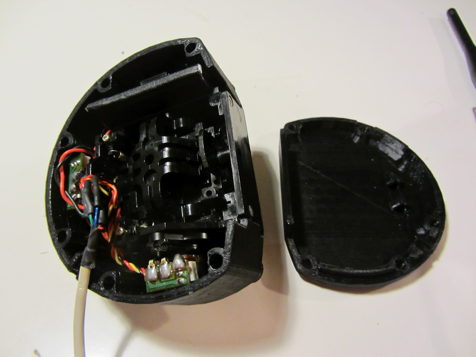
The left-hand controller, opened up.  The joystick assembly occupies nearly the entire interior.  There's just enough room for the battery, which is the black oblong object above the joystick.


The right-hand controller has a bit more going on.  The four mode-control buttons are placed where I can easily press them with my fingers while working the joystick with my thumb.  The USB charging/programming port is visible, right above the Arduino reset button.  This side also has the radio transmitter and antenna, and the main power switch.


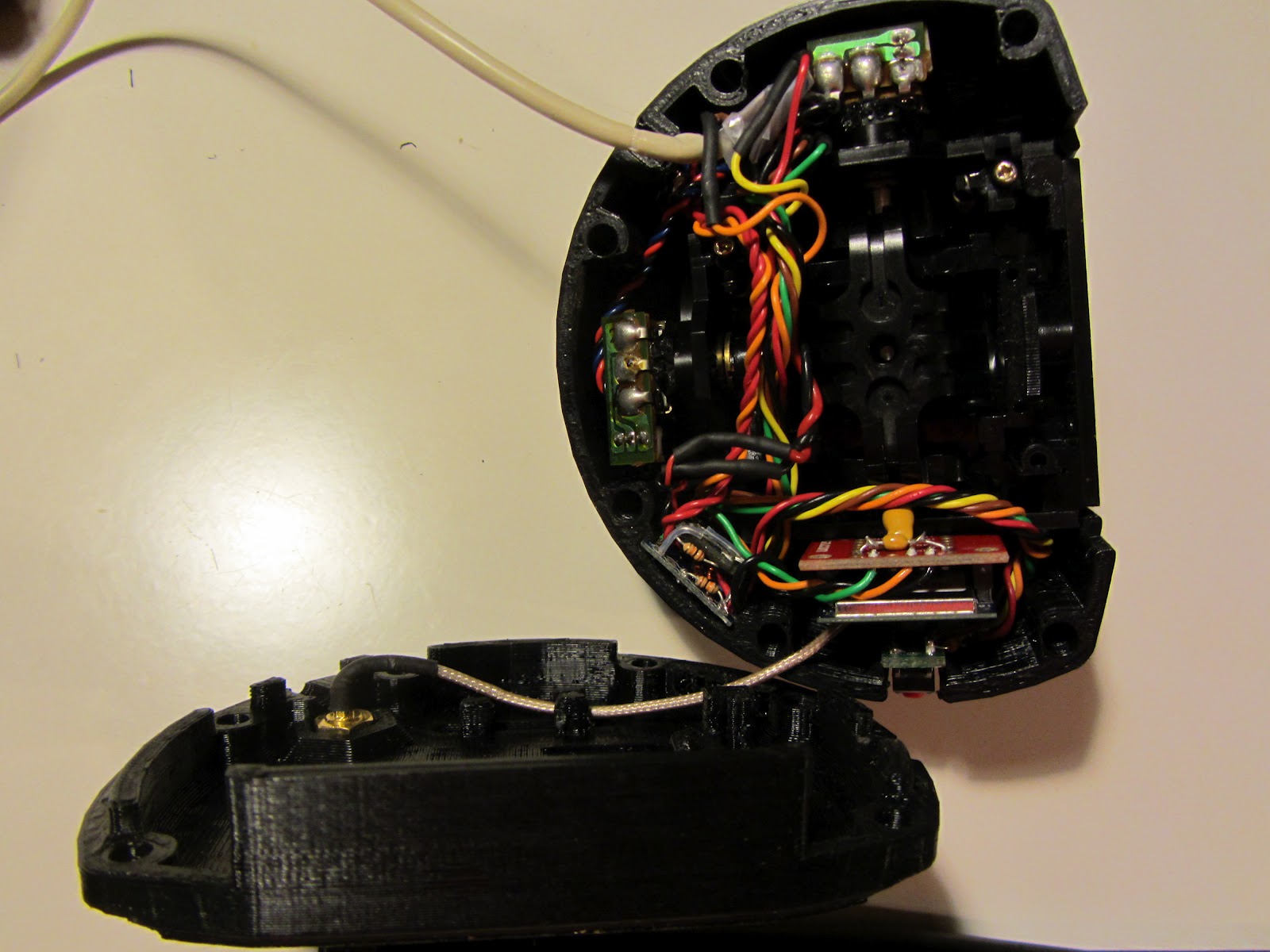
The right side controller opened up.  It's a bit hard to see what's going on - the modules are fairly tightly installed and obscured by wiring.  As with the left-hand controller, the joystick takes up most of the interior.  The Xbee radio module is at the bottom of the controller in this photo, and the Arduino/battery charger/serial converter assembly is just to the left of it.


Closeup on the control boards.  XBee carrier is on the left, with the wiring bundle to the mode select buttons snaking around it.  The Tantalum capacitor soldered across the XBee power terminals seems to be vital, I couldn't keep a reliable radio link without it.  The barely-visible control board is to the right.


Viewed from the opposite angle.  You can see the mode select buttons to the right, and the controller module to the left.  Admittedly it's hard to see how they're connected in this shot. The schematic posted above should make it clear.


All buttoned up, and ready to go to the convention!

On the robot itself, the biggest change has been replacing some of the steel parts of all four legs with printed parts.


After building the transmitter case, and some other test parts, I was confident enough in the strength of the 3D-printed parts to use them for the leg structure.  They seem to be holding up so far.  We'll see if any break over the convention weekend.

Tuesday, March 27, 2012

Replacing a broken leg

The final sections of the legs on my walking robots are made from a piece of waterjet cut steel, which the servo attaches to, welded to a short steel tube, containing the homebrew shock absorbers on the feet.  The weld between the servo mount piece and the tube is the weak point in the design.  One of these welds cracked after GenCon 2011.  I never got around to fixing it, instead using some Shapelock plastic to shore up the joint as a temporary patch that held well enough to become permanent.

At Wicked Faire 2012, another leg failed at the same spot, this one cracking badly enough for the shock tube to come completely loose.  I wasn't going to be able to patch this one back together short of re-welding it.


Since I now have access to a 3D printer, I decided to try and see if I could print out a replacement part  instead.  I wanted to keep the existing shock absorber tube, so after a few trial designs I made a two-part plastic assembly that clamps together around the tube and attaches it to the mounting tabs on the servo case.


The mounting frame is still using the same screws to mount to the servo tabs, as I'm still using the rubber mounting blocks to try and spare the servo gears the worst of the impact shocks from walking.

It seems to work, but I'll have to walk it around for a bit to make sure it's as durable as the old steel frames were.  Once I'm confident in the design I'll be printing out parts to rebuild all four legs this way.

This part is close to the maximum size the machine can print - I had to rotate it 45 degrees to fit it on the print bed.  This brings up another problem I've been having with the Makerbot recently.  Large prints, especially parts like this which stretch diagonally across the bed, tend to warp and shrink as they're being printed.  This can result in the part breaking free from the bed mid-print, or merely coming out curled and distorted.  Repeatedly cleaning and resurfacing the print bed, and even using a raft on some parts, didn't seem to help.

After reading some tips on the Makerbot forums, I started to suspect the ambient temperature and drafts.


It probably doesn't help that the printer has been moved to a back closet, next to a large window.  The window is kept closed - actually, it seems to be impossible to open - but it's still somehow cold and drafty in there.  Cold air blowing through the open printer frame can make the part cool prematurely and warp as it's being printed.

The preferred solution to this seems to be to cover the gaping open holes in the Makerbot frame with custom-cut acrylic sheets.  I didn't have those handy, so I've gone for the cheap but immediately available solution of taping paper over the openings instead.


Seems to be working so far.  No warping on this part, although I do have a fairly aggressive raft in place as well.